Introduction to the E2E-X10MF1-Z Proximity Sensor
The E2E-X10MF1-Z represents a specific model within Omron's extensive E2E series of cylindrical metal-body proximity sensors. Engineered for demanding industrial environments, this sensor is a shielded, DC 3-wire type with a nominal sensing distance of 10mm. Its defining characteristic is the "Z" suffix, indicating a normally open (NO) output configuration. Built with a robust nickel-plated brass housing, it is designed to deliver reliable non-contact detection of metallic objects, primarily ferrous metals like iron and steel, in applications ranging from machine automation to material handling systems. Its compact M18 form factor allows for easy integration into space-constrained machinery.
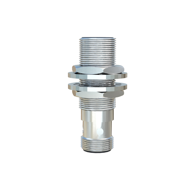
Key Technical Specifications and Operating Principles
Operating on a 12 to 24 VDC supply, the E2E-X10MF1-Z utilizes an electromagnetic induction principle. An oscillator circuit generates a high-frequency magnetic field at the sensing face. When a metal target enters this field, eddy currents are induced on the target's surface. This causes a change in the oscillation amplitude, which is detected by the sensor's circuitry, triggering a solid-state output switch. The shielded (flush-mountable) design allows for side-by-side installation without mutual interference and enables detection even when embedded in metal mounting brackets. Key specs include a 200mA max load current, less than 1ms response time, and protection circuits against short-circuit and reverse polarity. Its operating temperature range is typically -25 to 70°C, ensuring performance in varied conditions.
Electrical Wiring and Output Configuration
As a 3-wire DC sensor, the E2E-X10MF1-Z requires connection to a power source and load. The standard wire color coding is: brown for positive supply (+V), blue for negative supply (0V), and black for the output signal. In this "Z" version, the black output wire switches to 0V (sinks current) when a target is detected, completing the circuit to the load (e.g., a PLC input, relay, or indicator). This NPN (sinking) output is a common standard in many global regions. Proper wiring is critical: the load must be connected between the black wire and the positive supply. Incorrect wiring can lead to malfunction or permanent damage. Always refer to the official datasheet for definitive connection diagrams.
Mounting Considerations and Sensing Performance
Correct installation is paramount for optimal performance. The shielded design permits flush mounting in metal, but this affects the sensing distance. The effective sensing distance (Sn) can be reduced, and a derating factor must be applied per the manufacturer's guidelines. The sensor should be mounted securely using the provided hex nut, avoiding excessive torque. The sensing face must be kept free of obstructions like metal chips, dust, or coolant buildup, which can degrade performance. For consistent detection, the standard target is a square of mild steel (Fe 360) with thickness and side length equal to or greater than the sensor's diameter. Detection of non-ferrous metals like aluminum or copper will result in a reduced sensing range, typically 30-60% of the rated distance.
Typical Industrial Applications and Use Cases
The reliability and durability of the E2E-X10MF1-Z make it suitable for a vast array of automation tasks. Common applications include position verification of machine parts (e.g., confirming a cylinder is fully retracted or extended), workpiece counting on conveyor lines, end-of-travel limit sensing, and presence detection in assembly jigs. In packaging machinery, it can detect metallic components on high-speed lines. Its metal body offers excellent resistance to physical impacts, cutting fluids, and oils, making it ideal for CNC machine tools and automotive manufacturing cells. When used in control systems, it provides a crucial digital input for sequencing and safety interlocks.
Maintenance, Troubleshooting, and Best Practices
While designed for long service life, periodic inspection ensures continued reliability. Check for physical damage to the housing or cable. Clean the sensing face regularly with a soft cloth. Common issues include failure to detect targets, which may stem from incorrect wiring, insufficient power supply, target material/size mismatch, or excessive sensing gap. Constant output activation can indicate sensor damage or electrical noise interference. To mitigate noise, use shielded cables, keep high-voltage power lines separate from sensor wiring, and ensure proper grounding. Always power down the system before performing wiring checks or replacement. Keeping a stock of spares for critical processes minimizes downtime.