Introduction and Objective
This experiment report details the practical investigation of a photoelectric sensor control system. The primary objective is to demonstrate the operational principles of a diffuse-reflective photoelectric sensor in a simulated industrial control application. The experiment aims to verify sensor functionality, measure its effective sensing range, and integrate it into a simple control circuit to actuate a load, such as an LED or a relay, upon object detection. Understanding these fundamentals is crucial for the proper selection and implementation of sensors in automation, packaging, and material handling systems.
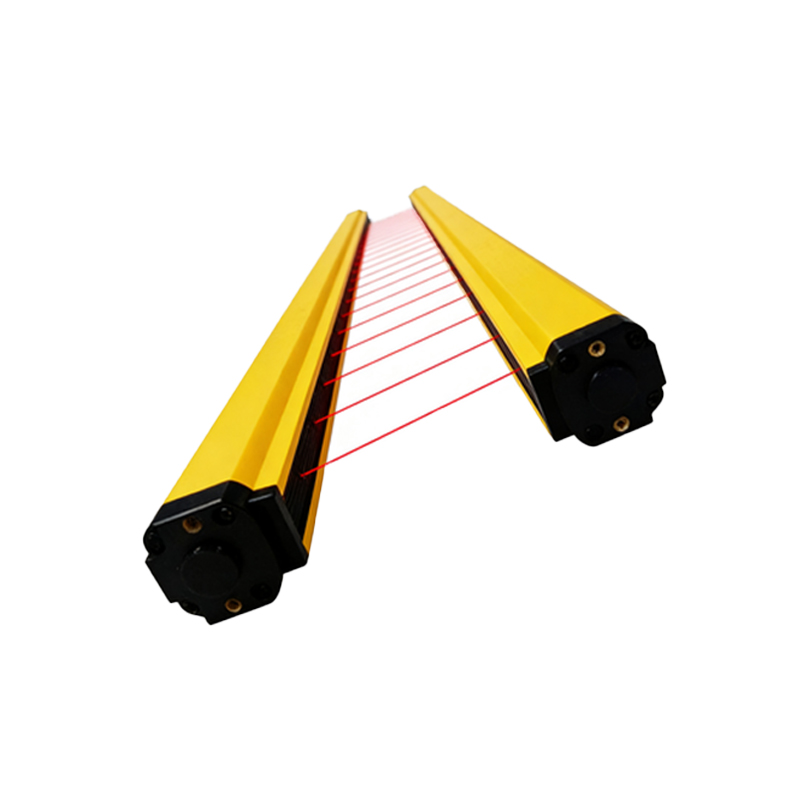
Theoretical Background and Operating Principle
Photoelectric sensors operate by emitting a beam of light, typically from an LED, and detecting changes in the received light signal. The diffuse-reflective type, which is the focus of this experiment, utilizes a single housing containing both the emitter and the receiver. The sensor detects an object when the emitted light is reflected off the object's surface and back to the receiver. The detection is highly dependent on the object's color, surface texture, and material. Key performance parameters include sensing distance, response time, and the presence of a sensitivity adjustment potentiometer to compensate for different environmental conditions and target reflectivity.
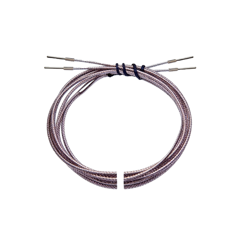
Experimental Apparatus and Components
The experimental setup comprised the following key components: A 24V DC diffuse-reflective photoelectric sensor (e.g., typical sensing range 0-300mm), a regulated 24V DC power supply unit, a multimeter for voltage and current measurements, a set of test objects (white paper, black paper, metallic sheet), a breadboard or terminal strip, connecting wires, a 5mm LED with a current-limiting resistor (e.g., 1kΩ), and a toggle switch. The sensor featured a digital output (typically NPN open-collector or PNP) and an indicator LED for visual confirmation of detection.
Circuit Configuration and Wiring Diagram
The sensor was connected as per its datasheet specifications. The brown wire (or +V) was connected to the positive terminal of the 24V DC supply. The blue wire (or 0V) was connected to the supply's negative terminal. The black wire (output signal) was connected in series with the LED and its current-limiting resistor, and then to the positive supply (for PNP type) or ground (for NPN type) to complete the circuit. A multimeter was placed in series to monitor the output current. All connections were double-checked for polarity and security before power application.
Experimental Procedure and Methodology
The procedure was executed in three phases. First, the basic functionality was tested by powering the sensor and observing its indicator LED. An object was moved in and out of the sensing field. Second, the sensing range was characterized. A highly reflective white target was moved axially away from the sensor face until the output just deactivated, noting the maximum stable detection distance. This was repeated with low-reflectivity black material. Third, the control aspect was verified by ensuring the external LED illuminated precisely when the sensor detected an object and turned off when the object was removed, confirming correct output switching.
Data Collection and Observed Results
The sensor's indicator and the controlled LED provided immediate qualitative results. Quantitatively, the maximum reliable sensing distance for a standard white test card was measured at 280mm, slightly below the rated 300mm, which is within normal tolerance. For the matte black paper, the maximum distance reduced significantly to approximately 80mm, demonstrating the impact of reflectivity. The sensor's response time was visually instantaneous. The output current, measured with the multimeter, was 20mA when active, sufficient to drive the LED brightly. The sensitivity adjustment was used successfully to tune detection for the black object at a fixed 100mm range.
Analysis and Discussion of Findings
The results confirm the core principle of diffuse-reflective sensing. The variance in detection range based on object color and surface finish is a critical design consideration. For instance, a system designed to detect white boxes may fail to detect dark ones without proper sensitivity calibration or margin. The fast response time validates its use in high-speed counting applications. The experiment successfully transformed a physical presence (the object) into an electrical control signal, which is the foundation of automated control loops. Potential error sources include ambient light interference, which was minimal in this lab setting but requires shielding or modulated light sources in industrial deployments.
Conclusion and Practical Applications
In conclusion, the experiment successfully demonstrated the control functionality of a diffuse-reflective photoelectric sensor. The system reliably detected objects within a variable range dependent on reflectivity and provided a switched output to control an external device. These sensors are indispensable in modern industry. Practical applications include object detection on conveyor belts, jam detection in machinery, part presence verification in assembly stations, and bottle counting in filling lines. Proper selection requires careful analysis of the target object, environmental conditions, required sensing distance, and output compatibility with the controller, such as a PLC.