Understanding the Basics of Photoelectric Sensor Symbols
Photoelectric sensor symbols are a standardized visual language used in electrical schematics and circuit diagrams. These symbols, governed by international standards like IEC 60617, represent the function of the sensor rather than its physical appearance. At their core, all photoelectric sensor symbols incorporate a basic element: a circle or a square representing the sensor housing, with internal graphical notations indicating its specific type. The key to interpretation lies in recognizing the internal icons for the light source (typically an LED represented by a diode symbol with outward arrows) and the receiver (a phototransistor or photodiode symbol). Understanding this foundational element is the first step in deciphering any photoelectric sensor schematic.
Decoding Common Symbol Variations
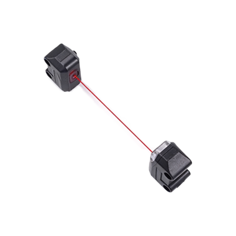
The primary variations in symbols correspond to the three main operating modes: through-beam, retro-reflective, and diffuse. A through-beam sensor symbol is distinctly represented by two separate components: a transmitter (Tx) and a receiver (Rx), placed opposite each other in the diagram, often connected by dashed lines indicating the light beam. The transmitter symbol shows the diode with outward arrows, while the receiver shows a phototransistor symbol. The retro-reflective sensor symbol combines both emitter and receiver into a single housing symbol. A unique addition is a small graphical element, often two angled lines, representing the integrated reflector or the target reflector itself. This indicates the light path returns to the same unit. The diffuse (proximity) sensor symbol also features a combined housing, but the light path is shown reflecting off a generic object, usually depicted as a simple block or irregular shape near the sensor.
Interpreting Electrical Connections and Outputs
Beyond the optical function, the symbol must clearly indicate the electrical interface. This is done through connection points or pins extending from the sensor housing. The number of pins varies (commonly 3 or 4 wires). A standard three-wire DC sensor symbol will show pins for positive supply voltage (typically +V or 24V), common negative (0V or GND), and the output signal. The output type is crucial and is indicated by the internal switch symbol. A solid-state NPN (sinking) output is shown with a transistor symbol inside the housing, with the emitter pointing toward the negative rail. A PNP (sourcing) output has the emitter pointing toward the positive rail. For a relay or mechanical contact output, a standard switch contact symbol is used. Always cross-reference these markings with the sensor's datasheet for voltage and current ratings.

Analyzing Special Function Indicators
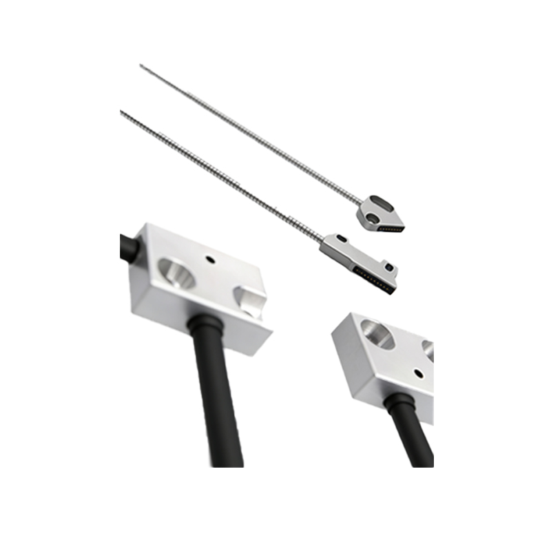
Modern photoelectric sensors include advanced features, and their symbols incorporate specific markers. A sensor with a built-in amplifier or logic controller might have a small rectangle or "amp" notation inside the housing. Timers or delay functions are indicated by the standard clock or "t" symbols adjacent to the output line. For light-on/dark-on operation, which defines the output state when the beam is received, a small notation like "L.On" or "D.On" may be placed near the output. Fiber-optic sensor heads, which are remote sensing elements, have a distinct symbol: the main amplifier unit has a standard sensor symbol, but the sensing head is shown as a small circle with a line representing the fiber cable connecting them. These indicators are essential for understanding the sensor's operational logic in the control system.
Practical Steps for Schematic Analysis
When faced with an unfamiliar photoelectric sensor symbol on a schematic, follow a systematic approach. First, identify the housing and determine if it is a single unit or separate Tx/Rx pair. Second, examine the internal graphics to classify it as through-beam, retro-reflective, or diffuse. Third, trace and label all electrical connections: power supply lines and the output signal line. Fourth, identify the output switching type (NPN/PNP/Relay) from the internal electronic symbol. Finally, look for any auxiliary markings indicating special functions like timers or logic modes. Always remember that the schematic symbol shows electrical function; mounting, range, and light source type (e.g., red, infrared, laser) are not depicted and must be verified from the part number and bill of materials.
Importance of Standards and Documentation
Reliance on standard symbols is non-negotiable for clear communication in electrical engineering. While most symbols follow IEC or ANSI standards, minor variations can exist between different manufacturers or legacy systems. Therefore, the diagram's legend or symbol list is the ultimate authority. If a symbol is ambiguous, consulting the specific sensor's technical data sheet is imperative. The datasheet provides the definitive symbol, pinout diagram, and all operational characteristics. Mastering the interpretation of these symbols enhances troubleshooting speed, ensures correct wiring during installation, and allows for accurate system design and modification, forming a critical skill for any professional working with industrial automation.