Understanding Proximity Sensor Types and Specifications
Before initiating any replacement procedure, it is paramount to correctly identify the existing sensor's type and specifications. Proximity sensors are broadly categorized into inductive, capacitive, and photoelectric types, each with distinct operating principles and target materials. Inductive sensors detect metallic objects, capacitive sensors respond to both metallic and non-metallic materials, and photoelectric sensors use light beams. The replacement sensor must match not only the physical form factor (e.g., cylindrical, rectangular, threaded or non-threaded body) but also the critical electrical specifications. These include the operating voltage (commonly 10-30V DC or 90-250V AC), output type (PNP/NPN, NO/NC), sensing range, and current rating. Installing an incorrect type can lead to system failure, damage to the sensor or controller, and potential safety hazards. Always refer to the machine's electrical diagrams and the original sensor's datasheet for verification.
Ensuring Proper Power Isolation and Lockout/Tagout
Safety is the non-negotiable first step in any industrial maintenance task. Never attempt to replace a proximity sensor on live equipment. Follow a rigorous Lockout/Tagout (LOTO) procedure to de-energize and isolate all power sources to the machine or control panel. This includes primary power circuits and any secondary control voltages. Use a verified multimeter to test for the absence of voltage at the sensor's connection points. Confirm that pneumatic or hydraulic systems that might cause unexpected machine movement are also depressurized and isolated. Proper LOTO protects personnel from electrical shock and prevents accidental machine activation during the replacement process, which could cause severe injury or equipment damage.
Disconnecting and Removing the Faulty Sensor
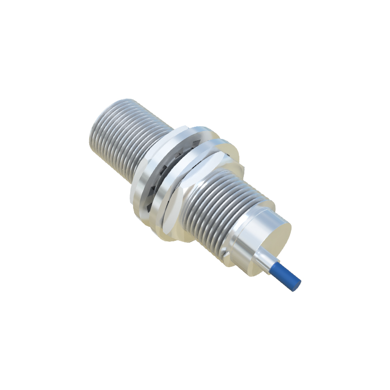
Once safety is confirmed, proceed to disconnect the sensor. Most industrial proximity sensors utilize quick-disconnect M12 or M8 connectors, while some may be hard-wired into junction boxes. For quick-disconnect types, ensure the connector is clean and undamaged before uncoupling. For hard-wired sensors, carefully note or photograph the existing wiring scheme—specifically which wire connects to the positive supply (+V), negative/ground (0V), and signal output line. Label each wire if necessary. Use appropriate tools to loosen the sensor from its mounting bracket or threaded hole. Avoid using excessive force that could damage the mounting threads or the housing of adjacent components. Inspect the mounting area for corrosion, debris, or damage that could affect the installation of the new unit.
Installation and Alignment of the Replacement Sensor
Install the new sensor by reversing the removal process. Ensure all sealing washers or O-rings are in place if the environment requires ingress protection (IP67, IP69K, etc.). Hand-tighten the sensor first to avoid cross-threading, then secure it to the specified torque if provided by the manufacturer. Proper alignment is critical for reliable operation, especially for cylindrical inductive sensors. The sensing face must be positioned correctly relative to the target object. The target should approach the sensor within its specified sensing range and along the correct axis (axial or lateral, depending on the model). Misalignment can significantly reduce the effective sensing distance and cause intermittent failures. Use non-ferrous alignment tools if needed to fine-tune the position before final tightening.
Wiring Verification and Polarity Check
Accurate wiring is essential. For sensors with quick-disconnect plugs, mating is straightforward, but ensure the connector is fully seated and locked. For hard-wired replacements, double-check your notes or photographs and connect each wire to the correct terminal. A common error is reversing the supply polarity for DC sensors or connecting an NPN output sensor to a PLC input card configured for PNP sourcing, or vice-versa. This will prevent the sensor from operating. Verify the wiring against the new sensor's datasheet, as color codes can vary between manufacturers (e.g., brown for +V, blue for 0V, black for output is common but not universal).
Functional Testing and Calibration
Do not assume the new sensor will work immediately upon power restoration. After completing the LOTO clearance procedure and re-energizing the system, conduct thorough functional tests. Use the target material (e.g., the specific metal part the machine uses) to trigger the sensor. Observe the sensor's indicator LED (if equipped) and monitor the signal on the PLC input module or control panel indicator. Check for consistency in detection at the maximum and minimum required distances. For adjustable or programmable sensors, you may need to calibrate the sensing distance or hysteresis. Test the sensor under the machine's normal operating cycle speed to ensure it can reliably detect fast-moving targets without missing counts. Document