Understanding Proximity Sensor Fundamentals
Proximity sensors are non-contact devices designed to detect the presence or absence of an object within a specified sensing range. They operate on various principles, primarily inductive, capacitive, and photoelectric. Inductive sensors detect metallic objects by generating an electromagnetic field. Capacitive sensors can detect both metallic and non-metallic materials by sensing changes in capacitance. Photoelectric sensors use a light beam, typically infrared, to detect objects. Understanding the core technology is the first step in proper application. Selecting the wrong type for a given material or environment is a common pitfall. Engineers must match the sensor's operating principle to the target object's properties and the environmental conditions, such as the presence of dust, moisture, or other sensors that might cause interference.
Step 1: Defining the Application Requirements
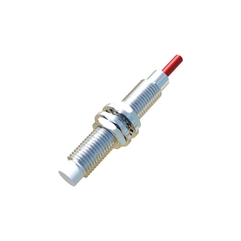
Before consulting any wiring diagram, clearly define the application's needs. Ask critical questions: What is the target material (metal, plastic, liquid)? What is the required sensing distance? What is the object's size and expected approach speed? What is the operating environment (temperature, contaminants, washdown requirements)? What output type is needed: discrete (PNP/NPN) or analog (4-20mA, 0-10V)? What is the power supply voltage (12-24V DC typical)? Documenting these parameters is essential for selecting the correct sensor model and understanding the subsequent wiring and setup steps. This initial analysis prevents costly errors and ensures system reliability.
Step 2: Selecting and Mounting the Sensor
Based on the requirements, select the appropriate sensor. Refer to the manufacturer's datasheet for specifications like nominal sensing distance (Sn), repeatability, and housing style (cylindrical, rectangular, ring-shaped). Mounting is critical. Ensure the sensor is securely fixed. For inductive sensors, maintain a clearance zone around the sensing face; metallic objects in this zone can affect performance. The diagrams below illustrate correct and incorrect mounting scenarios, highlighting the importance of maintaining proper distances from surrounding metal structures and other sensors to prevent mutual interference. Always follow the manufacturer's recommended mounting distances and use non-ferromagnetic mounting hardware.
Step 3: Interpreting the Wiring Diagram (2-Wire vs. 3-Wire)
Wiring diagrams are the blueprint for connection. Most industrial proximity sensors use a 3-wire DC configuration. The standard wire color coding is: Brown for DC+ (positive supply), Blue for DC- (negative supply or ground), and Black for the output signal. For a PNP (sourcing) sensor, the black wire switches the positive voltage to the load. For an NPN (sinking) sensor, the black wire switches the ground connection to the load. The accompanying diagram clearly labels these connections, showing the sensor, power supply, and the load (e.g., a PLC input module or relay). A 2-wire AC/DC sensor diagram is simpler, showing the sensor in series with the load and power supply, but attention must be paid to voltage drop and leakage current.
Step 4: Practical Wiring and Connection
With the diagram in hand, proceed with wiring. First, ensure power is OFF. Connect the power supply wires: brown to positive (+V) and blue to common/negative (0V). Connect the sensor's output wire (black) to the input terminal of your controller (PLC, relay, etc.). If using a PNP sensor with a PLC sinking input, or an NPN with a sourcing input, an interface relay may be required. Always use shielded cable for long runs or in electrically noisy environments, connecting the shield to ground at one end only. The diagram for this step includes icons for the power supply, sensor, PLC digital input, and protective fuse, illustrating a complete and safe circuit.
Step 5: Alignment, Testing, and Adjustment
After wiring, power on the system. Alignment is crucial for reliable detection. Use the target object and slowly bring it toward the sensor's sensing face along the axis of approach. Many sensors have a built-in LED indicator that lights up when an object is detected. Observe the exact point of detection. Verify that the sensing distance meets the specification and is repeatable. For adjustable sensors, use a non-metallic tool to fine-tune the sensitivity potentiometer if necessary, often to ignore smaller or background objects. A diagram here shows a technician using a calibration target at the specified sensing distance, with the sensor's LED illuminated, confirming correct operation.
Step 6: Troubleshooting Common Issues
Even with correct wiring, issues may arise. A systematic approach is key. If the sensor does not detect anything, check