Understanding the Core Challenge
Connecting a 5V photoelectric sensor directly to a 24V DC power supply is a common yet critical challenge in industrial automation. The fundamental issue is voltage mismatch. A sensor designed for 5V operation will be permanently damaged if subjected to 24V, as the excess voltage will overwhelm its internal circuitry, leading to component failure. The solution is not about rewiring the sensor itself, but about implementing an intermediary device to safely drop the voltage from the supply level to the sensor's required operating level. This process requires careful selection of components and adherence to proper electrical practices to ensure reliability and longevity of the system.
Essential Component: The Voltage Regulator
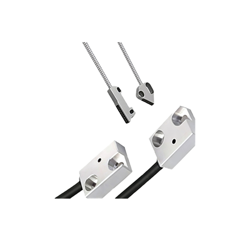
The most common and reliable method is to use a DC-DC voltage regulator, also known as a step-down converter or buck converter. This device efficiently converts a higher input voltage (24V) to a stable, lower output voltage (5V). When selecting a regulator, key specifications must be considered. First, ensure the input voltage range includes 24V. Second, the output must be a fixed 5V DC. Third, the output current rating must meet or exceed the sensor's current consumption, typically found in its datasheet. A regulator with a current rating of 1A or more is usually sufficient for most photoelectric sensors, providing a safe margin.
Alternative Method: Utilizing a Resistor Divider
For very low-current sensors in non-critical applications, a simple voltage divider circuit using two resistors can be theorized. However, this method is generally not recommended for industrial environments. Its output voltage is not regulated and will fluctuate with changes in the sensor's current draw or the supply voltage. It also wastes significant power as heat in the resistors, reducing efficiency. The lack of stability and protection makes the voltage divider an unreliable solution for ensuring consistent sensor operation, where the voltage regulator remains the professionally endorsed choice.
Step-by-Step Wiring Procedure
Begin by disconnecting all power sources. Identify the terminals on your 24V power supply: positive (+) and negative (-) or common (COM). Connect the input terminals of your 5V voltage regulator to these supply terminals, observing polarity: 24V+ to regulator Vin+, 24V- to regulator Vin-. Next, connect the output terminals of the regulator to your photoelectric sensor. The regulator's Vout+ (5V) connects to the sensor's positive supply wire (often brown or red). The regulator's Vout- (GND) connects to the sensor's negative supply wire (often blue or black). Finally, connect the sensor's output signal wire (often black, white, or yellow) to your controller's input, such as a PLC.
Critical Considerations for Stable Operation
Several factors are crucial for a robust installation. Always include an appropriately rated fuse on the 24V supply line to protect against short circuits. For the voltage regulator, consider adding small capacitors (e.g., 10µF electrolytic and 0.1µF ceramic) across its input and output terminals as recommended by its datasheet to filter noise and ensure stability. Secure all connections properly using terminal blocks or soldering, and protect the wiring from physical damage. Verify the output voltage of the regulator with a multimeter before connecting the sensor to confirm it is a steady 5V under load.
Verification and Troubleshooting Tips
After powering up the system, perform functional checks. Verify the sensor's indicator LED activates when its sensing condition is met. Use a multimeter to confirm the voltage at the sensor's power terminals is a stable 5V. If the sensor does not operate, first re-check all wiring connections for correctness and tightness. Measure the regulator's input to ensure 24V is present. If the output voltage is incorrect, the regulator may be faulty or overloaded. Ensure the total current draw of the sensor and any connected load does not exceed the regulator's rated output current. Consult the sensor and regulator datasheets for specific operational parameters.