Introduction to Electromagnetic Proximity Angle Sensors
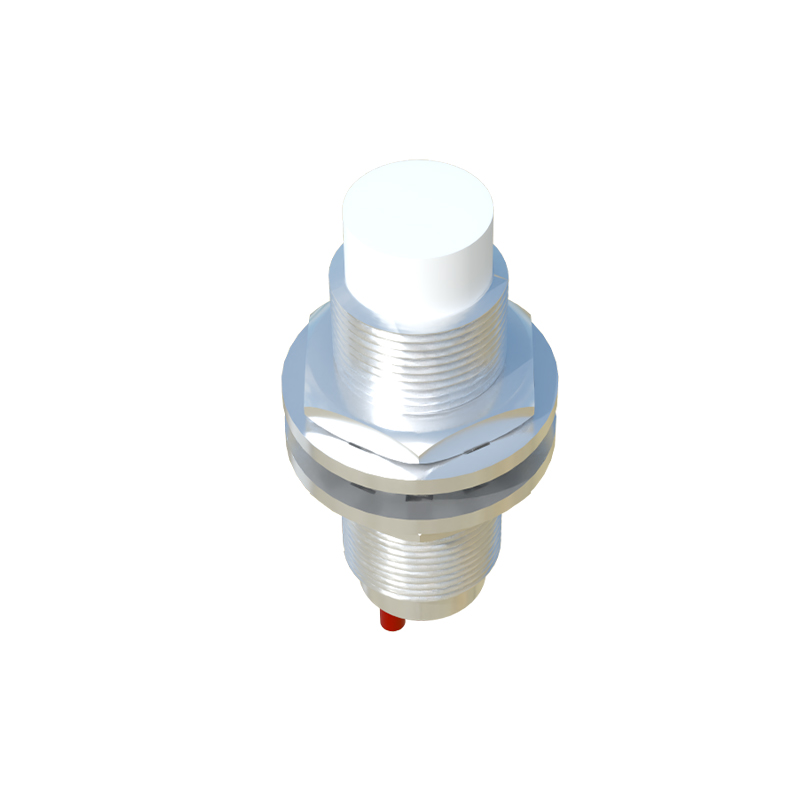
Electromagnetic proximity angle sensors are critical components in modern industrial automation and motion control systems. These devices detect the angular position or rotational movement of a target without physical contact, relying on electromagnetic field interactions. Typically, they consist of a stationary sensing element and a rotating target, often made of ferromagnetic material. The sensor generates an electromagnetic field, and as the target moves, it alters this field, allowing the sensor to determine the angle of rotation with high precision. This non-contact operation ensures minimal wear, long service life, and reliable performance in harsh environments, making them ideal for applications such as robotics, automotive steering systems, and industrial machinery. Their ability to provide accurate angular measurements contributes to enhanced control and efficiency in various electromechanical systems.
Fundamental Operating Principles
The core working principle of electromagnetic proximity angle sensors is based on Faraday's law of electromagnetic induction and the variation of magnetic reluctance. When an alternating current is applied to a coil within the sensor, it produces a time-varying electromagnetic field. A nearby ferromagnetic target, such as a gear or toothed wheel, interacts with this field. As the target rotates, its teeth or protrusions change the magnetic circuit's reluctance, modulating the electromagnetic field. This modulation induces a corresponding change in the sensor's output signal, typically in voltage or current. By analyzing these signal variations—such as amplitude, frequency, or phase shifts—the sensor can calculate the angular displacement. Advanced sensors may use multiple coils or Hall effect elements to improve resolution and accuracy, enabling precise detection of even minute angular changes without direct contact.
Key Components and Design Features
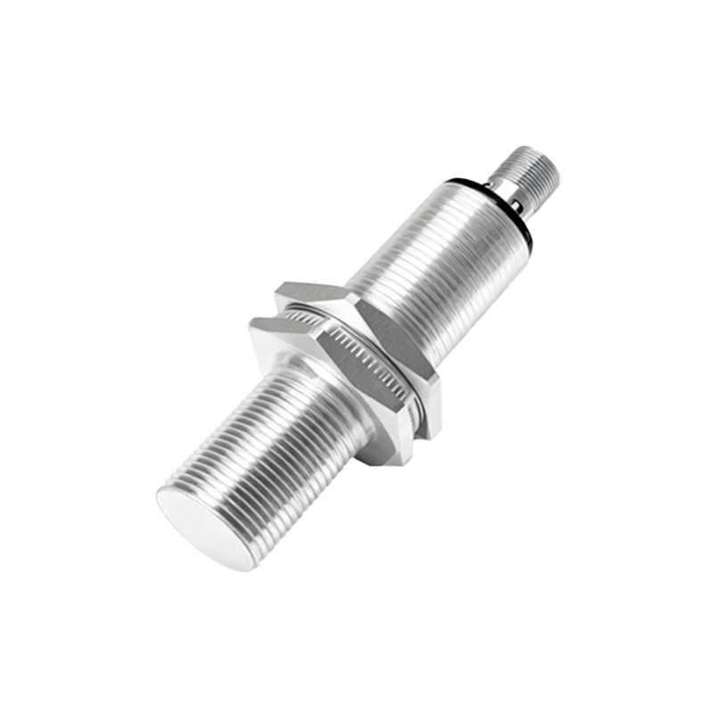
Electromagnetic proximity angle sensors comprise several essential components: a coil or winding to generate the electromagnetic field, a ferromagnetic core to focus the field, and signal processing circuitry. The target, usually made of steel or iron, is designed with specific geometries like teeth or slots to create predictable field disturbances. Sensor designs often incorporate shielding to minimize interference from external magnetic sources, ensuring stable operation. Additionally, modern versions integrate microcontrollers for digital signal processing, allowing for features like self-calibration, error compensation, and output interfaces such as analog voltage, PWM, or digital protocols like SPI. These design features enhance durability, with many sensors rated for high temperatures, vibration, and contaminants, suiting them for demanding industrial settings where reliability is paramount.
Signal Processing and Output Interpretation
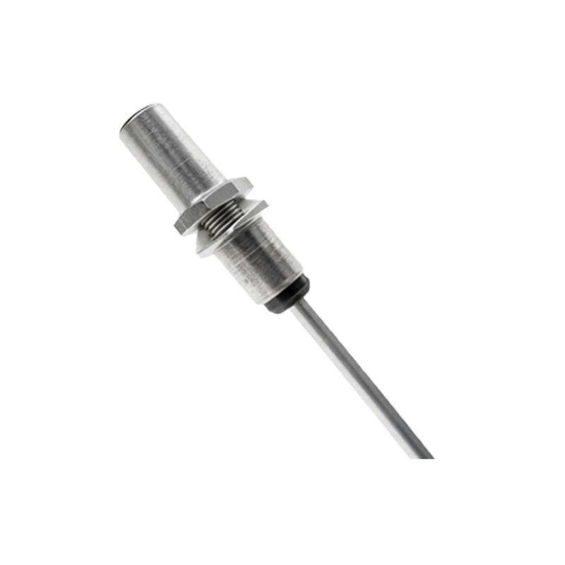
Signal processing is vital for converting raw electromagnetic variations into usable angular data. Initially, the sensor's coil output is an analog signal that fluctuates with target movement. This signal undergoes amplification and filtering to remove noise and harmonics. In digital sensors, an analog-to-digital converter digitizes the signal, followed by algorithmic processing to compute the angle based on pre-calibrated patterns. For instance, in inductive sensors, the phase shift between the excitation and output signals can indicate angular position. Outputs may be linear or rotary, with common formats including 0-10V analog, 4-20mA current loops, or encoded digital signals. Interpretation involves mapping these outputs to angular degrees, often with resolutions down to fractions of a degree, enabling precise control in applications like servo motors or valve positioning.
Applications in Industrial and Automotive Systems
Electromagnetic proximity angle sensors are widely deployed across industries due to their robustness and accuracy. In automotive systems, they monitor throttle position, steering angle, and pedal movement, contributing to safety features like electronic stability control. Industrial automation uses them for robotic arm positioning, conveyor belt alignment, and CNC machine tool feedback, where real-time angular data ensures operational precision. They also serve in renewable energy sectors, such as wind turbine pitch control, and in aerospace for actuator monitoring. Their non-contact nature makes them suitable for high-speed rotations and environments with dust, oil, or moisture, reducing maintenance needs and downtime. By providing reliable angular feedback, these sensors enhance system performance, efficiency, and safety in diverse electromechanical applications.
Advantages and Limitations
The primary advantages of electromagnetic proximity angle sensors include non-contact operation, which eliminates mechanical wear and extends lifespan; high accuracy and repeatability for precise control; and resilience in tough conditions like extreme temperatures or corrosive atmospheres. They offer fast response times and can detect both static and dynamic angles. However, limitations exist: sensitivity to electromagnetic interference from nearby equipment may require shielding, and performance can degrade with non-ferromagnetic targets unless specially designed. Calibration might be needed for optimal accuracy, and initial costs can be higher than contact-based sensors. Despite these drawbacks, their benefits often outweigh limitations, making them a preferred choice for critical angular sensing tasks in technology-driven fields.