Understanding the Core Function of Photoelectric Sensors
In industrial automation, photoelectric sensors are indispensable components for detecting the presence, absence, or position of objects without physical contact. They operate by emitting a beam of light (visible red, infrared, or laser) from a transmitter. A receiver then detects this light. The sensor's output signal changes state based on whether the light beam is received (in a through-beam or retro-reflective setup) or interrupted (in a diffuse reflective setup). When a sensor exhibits "no signal transmission," it means the control system is not receiving the expected switching signal, halting processes and causing downtime. This failure can stem from issues within the sensor itself, its installation, the target object, or the connected electrical system.
Primary Causes of Signal Failure
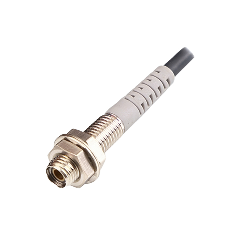
Several factors can lead to a photoelectric sensor failing to transmit a signal. First, power supply issues are common. An incorrect voltage (e.g., applying 24VDC to a 12VDC sensor), unstable power, or reversed polarity can prevent the sensor from operating entirely. Second, optical path obstruction is a frequent culprit. Dirt, dust, oil mist, or physical damage on the lens of either the transmitter or receiver can block or scatter the light beam, weakening it below the detection threshold. In through-beam applications, misalignment between the separate emitter and receiver units, even by a few millimeters, will break the beam path. Third, environmental conditions like intense ambient light (sunlight, welding arcs) can flood the receiver, making it unable to distinguish its own signal. Extreme temperatures or humidity outside the sensor's specified range can also cause internal component failure.
Systematic Troubleshooting Procedure
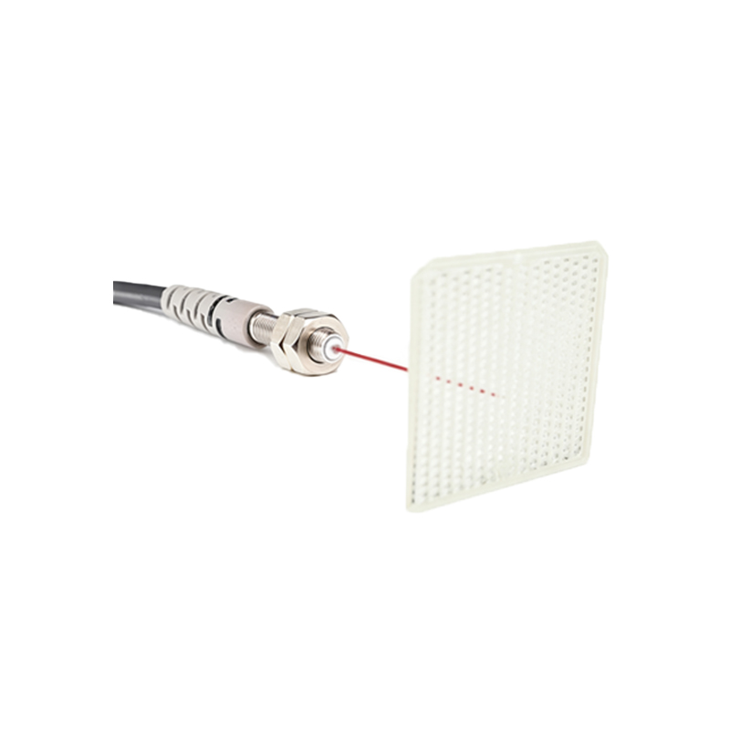
A methodical approach is key to resolving signal issues efficiently. Begin by verifying the electrical connections. Use a multimeter to confirm the correct supply voltage is present at the sensor's terminals. Check for loose wires, damaged cables, or poor connections in the conduit. Next, inspect the sensor's status indicator LEDs. Most modern sensors have power (usually green) and output (usually yellow or orange) LEDs. A lit power LED confirms basic functionality; a blinking or unlit LED often indicates a fault code described in the manual. If power is confirmed, clean the lenses carefully with a soft, lint-free cloth and isopropyl alcohol. For through-beam or retro-reflective sensors, perform a realignment. Temporarily bypassing the control logic with a known-good sensor can isolate whether the problem is with the sensor or the downstream PLC/controller.
Target Object and Application-Specific Checks
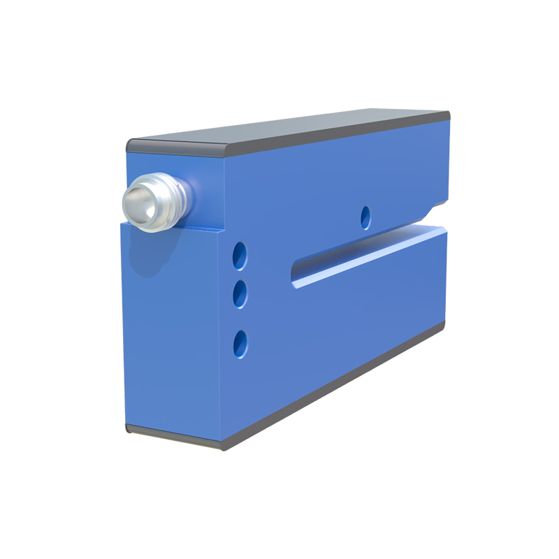
The characteristics of the target object itself can cause detection failure. The sensor must be suited for the object's size, color, material, and surface finish. A dark, matte, or transparent object may not reflect sufficient light back to a diffuse sensor. The object might be outside the sensor's specified sensing range or moving too fast for its response time. For small objects, the beam spot size might be too large. Ensure the object is consistently passing through the beam's detection point. In vibrating environments, the sensor or its mounting bracket may have loosened, causing intermittent alignment loss. Review the sensor's datasheet to confirm its specifications—such as sensing distance, beam pattern, and minimum object size—match the application requirements.
Electrical Interference and Output Circuit Issues
Electrical noise from nearby motors, variable frequency drives (VFDs), or welding equipment can induce false signals or mask the true signal. Ensure sensor cables are shielded, properly grounded, and routed away from power lines. The load connected to the sensor's output (e.g., a PLC input, relay coil) must be within its current and voltage ratings. An overloaded or short-circuited output can cause the sensor's internal protection to disable the output signal. For 3-wire DC sensors, ensure the correct type (NPN sinking or PNP sourcing) matches the PLC input card's configuration. A mismatch will result in no signal being read. Test the output by disconnecting it from the load and measuring the output voltage with a multimeter while triggering the sensor.
Advanced Diagnostics and When to Replace
If basic checks yield no results, advanced diagnostics may be necessary. An oscilloscope can monitor the sensor's output pin to see if a signal is generated internally but degraded by cable capacitance or noise. Some programmable sensors offer diagnostic data via IO-Link, providing detailed status on parameters like received light intensity, which can indicate gradual lens contamination or LED aging. Persistent failure after thorough troubleshooting often points to internal component failure. The LED light source has a finite lifespan, especially under high-temperature operation. The receiver phototransistor or the sensor's internal amplifier circuitry can also fail due to voltage spikes or aging. In such cases, replacement is the most reliable solution.
Preventive Maintenance Best Practices
Preventing signal loss is more efficient than troubleshooting it. Implement a regular maintenance schedule that includes visual inspection and lens cleaning. Secure all mounting hardware and cable connections to resist vibration. Use protective accessories like mounting brackets with fine-adjustment features for stable alignment, and install protective shrouds or air blowers in dusty environments. Select sensors with robust environmental ratings (IP67/IP69K) for harsh conditions. For critical applications, consider using sensors with built-in diagnostic functions or redundancy, such as dual-beam models. Keeping a log of sensor performance and environmental conditions can help predict failures before they cause unplanned downtime.