Understanding the Core Function: Signal Indication
The illumination of a proximity sensor's integrated LED is a fundamental diagnostic and operational feature. Contrary to a simple "on/off" indicator, this light serves as a direct visual representation of the sensor's switching state. When the sensor detects a target within its specified sensing range, its output circuit changes state. This change, typically the activation of a solid-state switch (PNP or NPN transistor), simultaneously powers the built-in LED. Therefore, a lit sensor light primarily confirms that the detection criteria have been met and the output is active. This immediate feedback is crucial during machine setup, troubleshooting, and routine operation, allowing for rapid verification of sensor functionality and alignment without the need for multimeters or PLC monitoring software in the initial stages.
Deciphering the Light Patterns: Status and Diagnostics
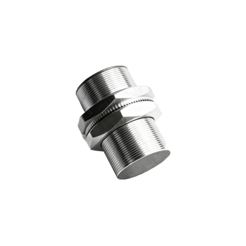
Modern proximity sensors often employ sophisticated light patterns to convey more than just a binary state. A steady, constant light usually signifies normal operation with an active output. However, many models incorporate blinking or color-changing LEDs for diagnostics. A slow blink might indicate a sensor operating in a marginal condition, such as at the extreme edge of its sensing range, signaling potential alignment issues. A fast blink or a different color (e.g., yellow instead of green) could denote an internal error, such as a short-circuit, overload condition on the output, or excessive supply voltage fluctuation. Some advanced sensors use specific blink codes, detailed in the datasheet, to identify issues like temperature warnings or contamination on the sensing face. Understanding these patterns is essential for predictive maintenance and preventing unplanned downtime.
Electrical Configuration and Wiring Implications
The behavior of the indicator light is intrinsically linked to the sensor's electrical design. In a 3-wire DC sensor, the LED is connected in parallel with the output switching element. For a normally open (NO) PNP sensor, the LED lights when the output transistor switches, connecting the output wire (usually black) to the positive supply voltage. In a normally closed (NC) configuration, the LED may be on when no target is present and turn off when a target is detected. It is critical to note that the LED's operation is independent of the load. The light will illuminate if the output circuit is activated, even if the load (e.g., a PLC input, relay coil) is disconnected, faulty, or wired incorrectly. This characteristic makes it a powerful tool for isolating faults between the sensor itself and the downstream control circuitry.
Target Influence and Sensing Characteristics
The act of the light turning on is a direct consequence of the sensor's interaction with a target. The sensing range, material, size, and approach direction of the target all influence the precise point of activation. For inductive sensors detecting metals, the effective sensing distance can vary based on the target's material (steel, aluminum, brass) and its size relative to the sensor's face. Capacitive sensors reacting to non-metallic materials are similarly affected by the target's dielectric constant. The indicator light provides real-time feedback for "teaching" or setting the optimal installation position. Engineers can observe the exact position where the light triggers as the target approaches, allowing for precise mechanical adjustment to ensure reliable detection while avoiding unintended actuation.
Troubleshooting Based on LED Behavior
A systematic approach to troubleshooting can be built around the sensor's LED. If the sensor light does not illuminate when a target is presented, the first step is to verify power supply voltage and polarity at the sensor's terminals. Next, check if the target is within the specified sensing range and is of the correct material. If the light operates correctly but the load does not respond, the fault lies downstream—check wiring to the load, the load's impedance, and any intervening fuses or connections. Conversely, if the LED remains constantly lit regardless of target presence, it may indicate a sensor failure (stuck output), a wiring fault causing a permanent voltage on the output line, or severe electrical noise interference triggering the sensor. A sensor that lights for incorrect or non-targets may be suffering from contamination, incorrect mounting (e.g., flush-mount sensor installed non-flush), or interference from adjacent metal structures or other sensors.
Environmental Factors and False Indication
Environmental conditions can significantly impact sensor performance and, consequently, the reliability of the LED indicator. Excessive ambient temperature can cause the sensor to operate outside its specifications, potentially leading to a drifting switching point where the light may flicker or activate unpredictably. Strong electromagnetic interference (EMI) from motors, welders, or frequency drives can induce currents in the sensor, causing false triggering and an erroneous LED indication. Contaminants like metal chips, oil, or coolant buildup on the