Understanding Photoelectric Sensor Fundamentals
Photoelectric sensors are indispensable components in modern industrial automation, utilizing light beams to detect the presence, absence, or distance of objects. Their operation hinges on three primary components: an emitter (light source), a receiver, and a signal processor. The emitter projects a beam of light—often infrared, visible red, or laser—towards the receiver. When an object interrupts or reflects this beam, the receiver detects the change in light intensity, and the signal processor converts this into an electrical output. Common operating modes include through-beam (opposed), retro-reflective, and diffuse (proximity) sensing. A thorough grasp of these fundamentals is the first critical step in implementing effective safety protocols, as it informs the selection, installation, and maintenance processes necessary for secure operation within complex machinery and safety systems.
Identifying Common Hazards and Failure Modes
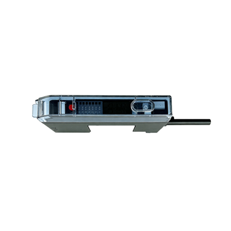
Despite their reliability, photoelectric sensors are subject to various hazards that can compromise safety. Environmental factors pose significant risks; accumulation of dust, dirt, oil mist, or condensation on the lens can attenuate or scatter the light beam, leading to false "no object" signals (failure to detect). Conversely, highly reflective backgrounds or ambient light interference from welding arcs or sunlight can cause false "object present" signals. Mechanical hazards include misalignment due to vibration or impact, which disrupts the optical path. Electrical issues such as voltage spikes, electromagnetic interference (EMI), or wiring faults can corrupt the sensor's output signal. Understanding these potential failure modes is paramount for conducting risk assessments and designing robust protective measures to prevent machine malfunctions or unsafe conditions.
Implementing Robust Mechanical and Environmental Protection
Selecting sensors with appropriate Ingress Protection (IP) ratings is a cornerstone of safety. For harsh environments, sensors rated IP67 or IP69K offer protection against dust ingress and high-pressure water jets. Utilizing protective housings, baffles, or sunshades can shield the lens from physical damage, direct sprays, and ambient light. For through-beam systems, ensuring rigid, vibration-resistant mounting for both emitter and receiver prevents misalignment. In areas with heavy particulate matter, installing air purge fittings or using sensors with built-in lens cleaning functions can maintain optical clarity. Regular inspection schedules should be established to check for lens contamination, housing integrity, and mounting stability, as these physical safeguards form the first line of defense against environmental and mechanical threats.
Ensuring Electrical Safety and Signal Integrity
Electrical safety begins with proper installation according to the manufacturer's specifications and relevant standards like IEC 60204-1. Utilize shielded cables, grounded correctly, to minimize EMI/RFI interference. Implement protective circuits such as fuses or surge suppressors on the power supply lines to guard against voltage transients. For critical safety functions, sensors with dual-channel outputs or short-circuit detection capabilities should be considered. It is vital to ensure the sensor's output signal is interfaced correctly with the machine's safety controller or programmable logic controller (PLC). Redundant wiring or using sensors with complementary (NO/NC) outputs can provide an additional layer of safety by allowing the control system to cross-check signal validity.
Integrating with Machine Safety Systems
A photoelectric sensor alone is rarely sufficient for personnel safety; it must be integrated into a holistic safety system. For safeguarding hazardous machine zones (e.g., robot cells, press brakes), safety-rated photoelectric curtains (light grids) conforming to standards like IEC 61496 (Type 2 or Type 4) must be used. These systems feature monitored outputs, redundancy, and self-checking circuits to achieve high Performance Levels (PL) or Safety Integrity Levels (SIL). The sensor's output should be wired to a safety relay or a safety-rated PLC input. The safety logic must be designed to trigger a safe state—typically a Category 0 or Category 1 stop—upon beam interruption. Regular validation testing of the entire safety function, including the sensor, wiring, and logic solver, is mandatory to ensure ongoing reliability.
Adhering to Standards and Best Practices
Compliance with international and regional standards is not optional for safety applications. Key standards include IEC 60947-5-2 for proximity sensor specifications, IEC 61496 for electro-sensitive protective equipment (ESPE), and ISO 13849-1 for the design of safety-related control systems. Best practices involve conducting a thorough risk assessment for each application, selecting sensors with appropriate safety certifications (e.g., TÜV, UL), and documenting all safety system designs, installations, and modifications. Personnel involved in installation, maintenance, and troubleshooting must receive specific training on the safety principles and functionality of the photoelectric systems in use. A culture of safety, supported by adherence to standards and continuous training, is the ultimate protective measure.
Establishing a Proactive Maintenance and Testing Regime
Predictive and preventive maintenance is crucial for sustained safety performance. Develop a scheduled maintenance plan that includes visual inspections, functional tests, and calibration checks as recommended by the manufacturer. Use alignment indicators or dedicated test tools to verify beam strength and alignment. Log all maintenance activities and any recorded incidents of false triggering or failure to detect. Periodically perform a full functional safety test of the integrated system to verify that the intended safe machine response occurs within the required time. By treating the photoelectric sensor as a critical safety component with a defined lifecycle and maintenance schedule, potential failures can be identified and rectified before they lead to a hazardous event.