Introduction to Photoelectric Sensor Wiring
Photoelectric sensors are indispensable components in modern industrial automation, enabling non-contact detection of objects through light beams. Proper wiring is fundamental to ensuring these sensors operate reliably within complex control systems. This guide delves into the core principles and practical steps for correctly connecting photoelectric sensors, covering common configurations, wire color standards, and essential safety considerations. Understanding these wiring fundamentals helps prevent system downtime, enhances operational safety, and maximizes sensor performance across diverse applications, from packaging lines to material handling systems.
Core Wiring Components and Terminology
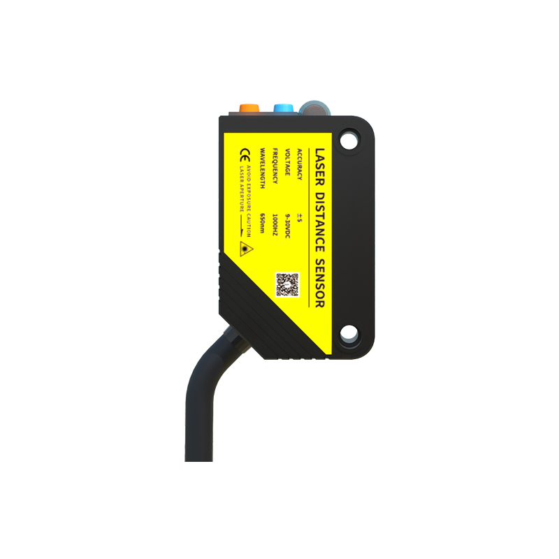
A standard photoelectric sensor typically features a cable or terminal block with several conductors. The primary wires include a brown wire for the positive DC supply voltage (often +24V DC), a blue wire for the 0V common or negative supply, and a black wire as the switched output signal. Some models include a white wire for complementary output or function programming. The load, such as a programmable logic controller (PLC) input or a relay coil, is connected between the black output wire and the positive supply. It is crucial to consult the specific sensor's datasheet, as wire colors and functions can vary by manufacturer and model, especially for AC-powered units or those with analog or IO-Link capabilities.
Standard DC 3-Wire Sinking and Sourcing Configurations
The majority of modern DC photoelectric sensors utilize a 3-wire configuration, operating as either sinking (NPN) or sourcing (PNP) devices. This refers to the switching action of the output transistor in relation to the common (blue) wire. In a PNP (sourcing) sensor, the black output wire switches the positive voltage to the load. The load is connected between the black wire and the common (blue). When the sensor detects an object, it "sources" current from the brown wire, through its internal switch, out the black wire, and to the load. Conversely, an NPN (sinking) sensor switches the negative or 0V side. Here, the load is connected between the positive supply and the black wire. Upon detection, the sensor "sinks" current from the load, through the black wire, to the common (blue). Matching the sensor's type (PNP/NPN) to the controller's input circuit is critical for proper operation.
Wiring Connection Procedures and Best Practices
Begin by disconnecting all power sources to the system. Verify the sensor's operating voltage and output type from its nameplate or documentation. For a standard DC PNP sensor, connect the brown wire to the +24V DC terminal, the blue wire to the 0V DC terminal, and the black output wire to the input terminal of your controller (e.g., PLC). Always use ferrules or properly stripped wire ends secured in tightened terminal blocks to prevent loose connections. Route sensor cables away from high-voltage power lines and motor drives to minimize electromagnetic interference (EMI), which can cause erratic switching. Employ conduit or cable carriers in areas with potential physical abrasion or exposure to oils and coolants.
Shielded Cables and Noise Immunity Strategies
In electrically noisy industrial environments, using shielded cable is highly recommended for photoelectric sensor connections. The cable's shield, typically a braided or foil layer, must be grounded at only one end—usually at the control panel end—to create a path for diverting EMI away from the signal conductors. Avoid grounding both ends, as this can create ground loops and induce current. For long cable runs exceeding the manufacturer's recommended distance (often 100 meters for standard models), consider using sensors with built-in noise immunity features or signal amplifiers. Proper grounding of the sensor housing itself, if metallic, further enhances system stability.
Troubleshooting Common Wiring Issues
Several symptoms point to wiring problems. If a sensor fails to power on, check for voltage between the brown and blue wires. Incorrect polarity (swapping brown and blue) can damage some solid-state sensors. If the output seems erratic or the sensor latches on, investigate for voltage drops over long wires, insufficient wire gauge, or electrical noise interference. A sensor that remains constantly on might indicate a wiring error where the load is missing or incorrectly placed, effectively short-circuiting the output. Using a digital multimeter to check continuity, voltage levels, and for short circuits is a fundamental diagnostic step. Always reference the sensor's diagnostic LED indicators, which provide vital status information about power, output state, and signal strength.
Safety Precautions and Regulatory Compliance
Adherence to electrical safety standards such as NFPA 79, IEC 60204-1, and local regulations is non-negotiable. Ensure all wiring complies with the required voltage, current, and insulation ratings. Implement appropriate overcurrent protection, such as fast-acting fuses or circuit breakers, in the supply line. For systems involving machinery safety, such as light curtains or safety-rated area scanners, follow the stringent wiring and validation procedures outlined in standards like ISO 13849 and IEC 61496. Lock-out/Tag-out (LOTO) procedures must be strictly followed during installation or maintenance to prevent accidental energization. Remember, correct wiring is not merely about functionality; it is a cornerstone of personnel and equipment safety.