Introduction to Embedded Proximity Sensors
Embedded proximity sensors are indispensable components in modern industrial automation, designed for flush mounting in metal to detect objects without physical contact. These sensors operate on the principle of electromagnetic field generation and disturbance detection. Among the various output configurations available, the NPN sinking output is a prevalent and critical type, especially in global manufacturing contexts. This article delves into the technical specifics, wiring, and application considerations of NPN output in embedded inductive proximity sensors.
Defining NPN Sinking Output
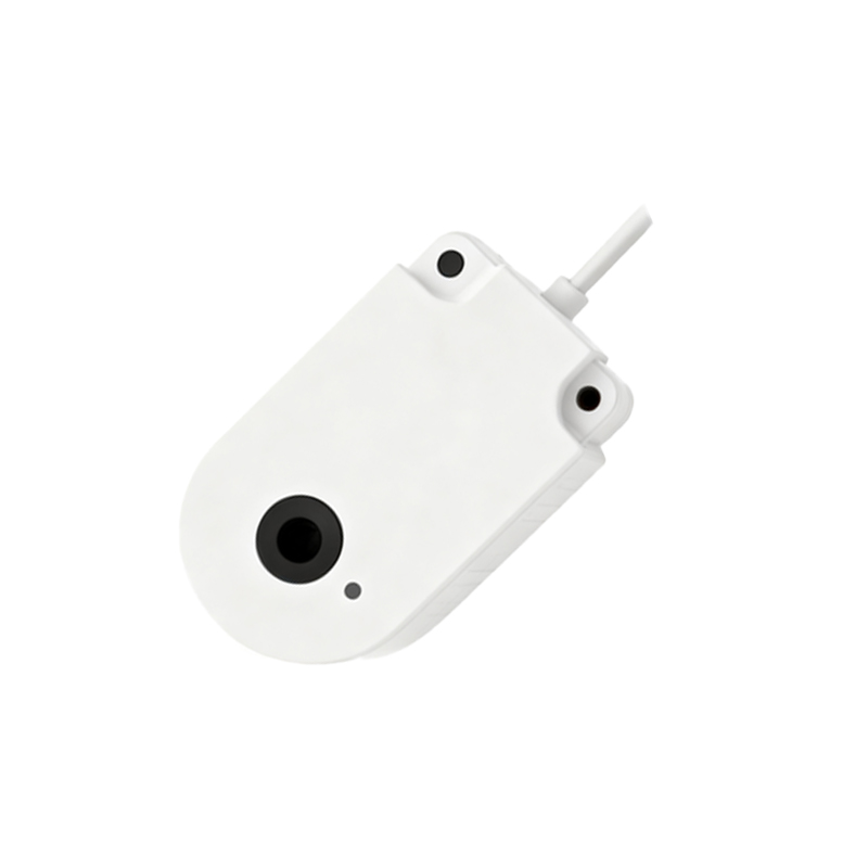
An NPN output in a proximity sensor refers to the type of transistor used in its switching circuit. In this configuration, the output transistor is an NPN bipolar junction transistor. The term "sinking" describes its function: when an object is detected, the transistor activates, connecting the output signal line (usually the black wire) to the common negative voltage (0V or ground). This creates a current path where the load current "sinks" into the sensor's output terminal, flowing to ground. Essentially, the sensor acts as a switch to ground, completing the circuit for the connected load, such as a PLC input or a relay coil.
Typical Wiring Configuration
A standard three-wire DC embedded proximity sensor with NPN output has brown, blue, and black wires. The brown wire connects to the positive DC supply voltage (typically +12V or +24V). The blue wire connects to the power supply common (0V or ground). The black wire is the switched NPN output signal. To connect a load, one terminal is linked to the positive supply, and the other terminal is connected to the sensor's black output wire. When the sensor detects a target, the internal NPN transistor turns on, connecting the black wire to the internal ground (blue wire), thus allowing current to flow through the load to complete the circuit and activate it.
Key Electrical Characteristics
Understanding the electrical specifications is crucial for reliable system integration. The load connected to an NPN output must be compatible with the sensor's voltage and current ratings. The maximum switching current, often around 200mA, must not be exceeded to prevent transistor damage. The residual voltage, or voltage drop across the transistor when "on," is typically less than 1.5V. This small voltage drop means the signal to the PLC will be very close to 0V when active, ensuring a clear logic-low signal. The off-state leakage current is minimal, usually in the microampere range, preventing false triggering.
Advantages in Industrial Applications
The NPN sinking output configuration offers several practical benefits. It is the standard in many regions, including Europe and Asia, ensuring wide component compatibility. From a safety and noise immunity perspective, having the active signal at 0V (ground potential) can be advantageous in certain control logic designs, as it may reduce susceptibility to electrical noise in some installations. Furthermore, when interfacing with many programmable logic controllers (PLCs), the sinking input module is designed to work seamlessly with NPN sensor outputs, simplifying wiring and reducing interface complexity.
Comparison with PNP Sourcing Output
It is essential to contrast NPN sinking with its counterpart, the PNP sourcing output. While an NPN sensor switches the negative side, a PNP sensor switches the positive side, providing a voltage signal when active. The choice between NPN and PNP often depends on regional standards and the specific input card of the controller. A common rule of thumb is that NPN sensors are typically used with PLC sinking input modules, where the PLC provides the positive voltage to the load, and the sensor completes the path to ground.
Installation and Mounting Considerations
For embedded (flush-mountable) inductive sensors, proper installation is key to performance. The sensor can be mounted flush in a metal bracket without loss of sensing range, as its electromagnetic field is concentrated at the front face. However, ensuring a non-ferrous metal target of sufficient size and thickness is critical for reliable detection. The surrounding metal must also be free of burrs to prevent damage to the sensor's active face. Always adhere to the specified mounting torque and maintain the recommended lateral and axial clearance from other metal objects to avoid mutual interference.
Troubleshooting Common Issues
System malfunctions often stem from wiring errors or environmental factors. If an NPN sensor fails to trigger, verify the wiring: ensure the brown wire is connected to positive, blue to negative, and the load is correctly placed between the positive supply and the black wire. Use a multimeter to check if the output voltage on the black wire switches from near supply voltage (off-state) to near 0V (on-state