Wiring a laser displacement sensor correctly is crucial for ensuring accurate measurements, system safety, and reliable operation. While specific steps vary by manufacturer and model, the general principles remain consistent. This guide provides a comprehensive overview of the standard wiring process, key considerations, and best practices.
Before beginning any wiring work, the foremost step is to consult the sensor's official datasheet and installation manual. These documents contain the definitive wiring diagram, pin assignments, voltage ratings, and any model-specific warnings. Ignoring this step risks damaging the sensor or connected equipment.
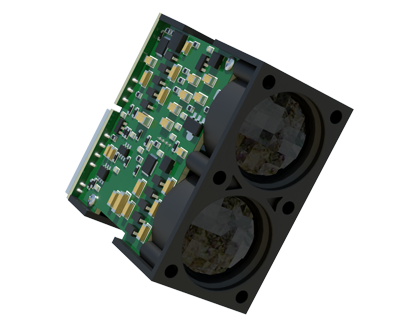
Typically, a laser displacement sensor features a connector or a set of terminals for power, output signals, and sometimes communication. The most common configuration involves three main connections: power supply, output signal, and ground.
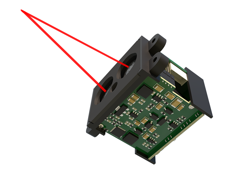
1. Power Supply Connections
Most industrial laser displacement sensors operate on DC power, commonly 12-24V DC. The datasheet will specify the acceptable voltage range (e.g., 10-30V DC).
- Identify the V+ (or +Vs) terminal/wire. This is the positive power input.

- Identify the V- (or 0V, GND) terminal/wire. This is the negative power input and the common ground.
Connect these to a stable, regulated DC power supply that matches the specifications. Using an unstable or incorrect power source can lead to measurement noise or sensor failure. Always ensure the power is OFF during connection.
2. Output Signal Connections
The type of output determines the wiring. Common outputs are analog (e.g., 0-10V, 4-20mA), digital (NPN/PNP transistor), or serial communication (RS-422, Ethernet).
- Analog Output (Voltage or Current): For a voltage output (e.g., 0-10V), you will typically have a separate output wire (often labeled OUT or Vout). This wire connects to the analog input channel of your controller (PLC, data logger). The ground is usually shared with the power ground. For a 4-20mA current loop output, it is wired in series with the receiving device and the power supply, following the specific loop diagram.
- Digital (Switch) Output (NPN/PNP): These are often open-collector outputs used for limit detection.
* NPN Type (Sinking): The output wire acts as a switch to ground (0V). When active, it connects the load to ground. The load (e.g., PLC digital input) is connected between the sensor's output wire and the positive supply (+V).
* PNP Type (Sourcing): The output wire acts as a switch to the positive supply. When active, it provides +V to the load. The load is connected between the sensor's output wire and ground.
Mismatching NPN and PNP with your controller's input circuit is a very common wiring error. Always verify compatibility.
3. Communication & Auxiliary Wires
Sensors with serial communication (like RS-422) will have multiple wires for data transmission (Tx+, Tx-, Rx+, Rx-) and may require a separate shield connection. Ethernet/IP sensors will use a standard RJ45 connector. Some sensors also have wires for external trigger input, alarm output, or teaching (setting a reference point). Refer to the manual for each wire's function.
Critical Wiring Practices:
- Use Proper Cabling: Employ shielded cables to protect the sensitive measurement signals from electromagnetic interference (EMI). For analog signals, twisted-pair cables are recommended.
- Grounding/Shielding: Connect the cable shield to a stable earth ground point, typically at the controller end only, to prevent ground loops. Do not connect the shield at both ends unless specified.
- Secure Connections: Use crimp terminals or soldered connections for reliability. Ensure wires are firmly seated in terminal blocks to prevent intermittent faults caused by vibration.
- Power Sequencing: It is generally good practice to apply power to the controller/receiving device before powering the sensor, and to power down in the reverse order.
- Safety First: Always lock out/tag out electrical panels before working. Double-check all connections against the diagram before applying power.
Post-Installation Check:
After wiring, power on the system. Observe the sensor's indicator LED (if present); it usually shows power status and output activity. Use a multimeter to verify the output voltage or current at known measurement points. Test the sensor's response by moving a target through its measurement range and monitoring the output on your controller or display.
Incorrect wiring can lead to no signal, incorrect readings, erratic behavior, or permanent hardware damage. Taking a methodical approach—studying the manual, identifying each wire's purpose, following good electrical practices, and testing thoroughly—will ensure a successful installation. When in doubt, contact the sensor manufacturer's technical support for clarification.