Introduction to Detection Distance Error
In industrial automation, photoelectric sensors are fundamental components for object detection, positioning, and counting. A critical performance parameter is the rated detection distance, which specifies the maximum operational range under ideal conditions. However, in practical applications, the actual detection distance often deviates from this rated value, leading to what is termed "detection distance error." This discrepancy can cause system malfunctions, production line stoppages, or quality control issues. Understanding the sources of this error is paramount for system designers and maintenance engineers to ensure robust and reliable operation. The error is not a single-factor phenomenon but a complex interplay of sensor characteristics, target properties, and environmental conditions.
Primary Factors Influencing Distance Error
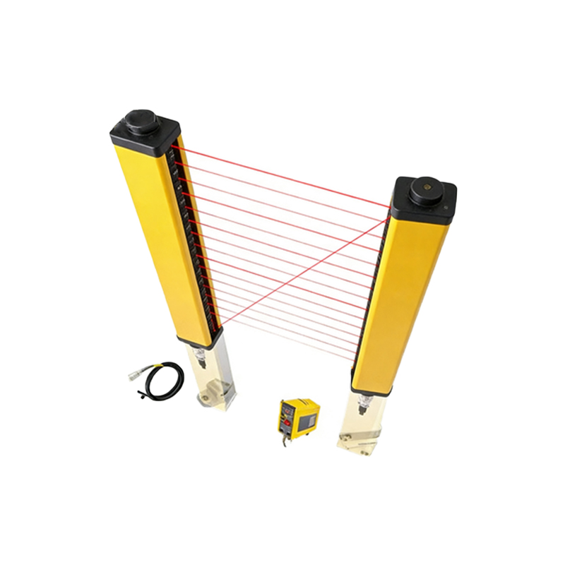
Several key factors contribute to variations in the effective detection range of photoelectric sensors. First, the characteristics of the target object itself are paramount. The size, shape, color, surface finish, and material composition significantly affect light reflection. A small, dark, matte, or non-metallic target will reflect less light back to the receiver compared to a large, bright, glossy, or metallic one, effectively reducing the detectable distance. Second, sensor alignment and mounting play a crucial role. Even minor angular misalignment between the emitter and receiver (in thru-beam types) or between the sensor and the target (in reflective types) can drastically shorten the operational range. Vibration or mechanical shock can exacerbate this misalignment over time.
Environmental and Operational Interferences
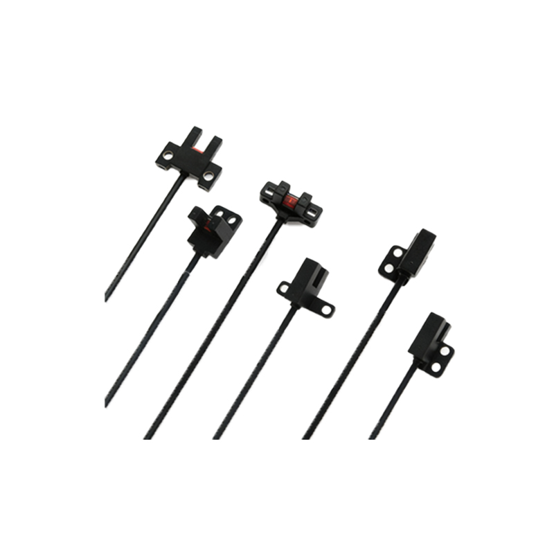
The operating environment is a major source of detection distance error. Ambient light is a classic interferent; strong sunlight or light from other machinery can saturate the sensor's receiver, causing false triggers or requiring the target to be much closer to overcome the noise. Temperature fluctuations affect the performance of the sensor's electronic components and the light-emitting diode (LED), potentially altering the intensity and wavelength of the emitted light. Contaminants such as dust, oil mist, steam, or condensation on the sensor lens can attenuate the light beam, scattering or absorbing the signal. Additionally, electrical noise from nearby motors, variable frequency drives, or welding equipment can interfere with the sensor's signal processing circuitry, leading to unstable detection.
Sensor Type and Technology Impact
The inherent design and technology of the photoelectric sensor dictate its susceptibility to distance error. Diffuse reflective sensors, which rely on light bouncing directly off the target, are most sensitive to target color and surface properties, leading to higher potential error. Retro-reflective sensors use a reflector and are less dependent on target finish but can be fooled by shiny objects that reflect light directly. Thru-beam sensors, with separate emitter and receiver units, offer the longest and most stable detection distances with minimal error related to target appearance, but they are more susceptible to alignment issues. Background suppression sensors and fixed-field sensors are designed to minimize errors caused by background objects or varying surface reflectivity, offering more consistent detection points.
Quantifying and Compensating for Error
Manufacturers typically specify a "correction factor" or provide derating graphs in datasheets. For instance, a sensor rated for 10 meters might have a correction factor of 0.5 for a matte white target, meaning the effective range is 5 meters. Engineers must apply these factors during system design. To compensate, setting the sensitivity potentiometer or using teach-in functions based on the actual target under real conditions is essential. Providing a sufficient "safety margin" or "derating" (e.g., using a sensor with a rated distance 1.5 to 2 times the required application distance) is a standard industry practice to account for cumulative error sources and ensure long-term reliability despite component aging.
Practical Mitigation Strategies and Best Practices
Implementing systematic mitigation strategies is key to minimizing detection distance error. Proper sensor selection is the first step: choose a sensor type whose technology best matches the application (e.g., background suppression for inconsistent targets). Ensure precise mechanical mounting and alignment, using alignment tools or indicators provided by the sensor. Install protective housings or air purgers to keep lenses clean from dust and condensation. Use shades, hoods, or filters to shield the sensor from ambient light interference. Employ sensors with modulated LED light and synchronous detection circuits, as they are highly immune to ambient light. For critical applications, regular preventive maintenance schedules should include checks for lens cleanliness, mounting stability, and verification of detection consistency with a standard test target.
Conclusion and System Integration Considerations
Detection distance error is an inherent challenge in photoelectric sensing, but it is manageable through informed engineering practices. A holistic approach that considers sensor selection, mechanical design, environmental hardening, and operational margins is necessary for success. During system integration and commissioning, testing under the full range of expected operating conditions—with different target samples, at temperature extremes, and under typical ambient light and vibration levels—is crucial. By acknowledging and proactively addressing the factors that contribute to distance error, engineers can design automation systems that are not only functional but also resilient, maintaining high uptime and precision throughout their operational lifecycle.