Introduction to Photoelectric Sensor Output Signals
In the realm of industrial automation and control, photoelectric sensors are indispensable for detecting the presence, absence, or position of objects. While digital outputs (like NPN/PNP) are common for simple on/off signaling, many advanced applications require a more nuanced data stream. This is where analog output signals, specifically millivolt (mV) outputs, become critical. A photoelectric sensor with a millivolt output provides a voltage signal that is directly proportional to the amount of received light or the measured distance. This continuous signal, typically ranging from 0 mV to a few hundred or thousand millivolts, allows for precise monitoring and control, enabling systems to respond not just to an object's presence, but to its precise position, size, opacity, or reflectivity.
The Principle of Millivolt Generation
The core of a photoelectric sensor is its receiver, usually a photodiode or phototransistor. When light from the sensor's emitter strikes this receiver, it generates a small photocurrent. This current is inherently analog and varies linearly with the intensity of the incident light. An internal transimpedance amplifier (TIA) is then employed to convert this minute photocurrent into a usable voltage signal. The gain of this amplifier circuit is carefully calibrated so that the full range of expected light intensity corresponds to a standardized millivolt output range, such as 0-100 mV or 0-5000 mV (5V). For instance, in a retro-reflective sensor, an unobstructed beam might yield 100 mV, while a partially blocking object would yield an intermediate value like 45 mV, and a complete blockage would drop the signal to near 0 mV.
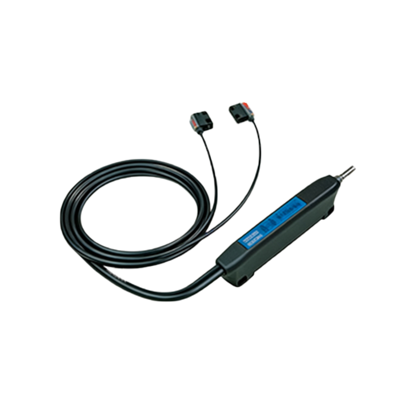
Key Applications and Advantages
The primary advantage of mV output sensors lies in their application for precision measurement and analog control. Common use cases include edge guidance in web processing (e.g., paper, film, textiles), where the sensor monitors the edge position and provides a continuous signal to a controller for real-time correction. They are also used for transparency detection, distinguishing between clear, tinted, and opaque materials based on light transmission. In contrast measurement, they can detect subtle differences in surface color or reflectivity. The millivolt signal offers high resolution and fast response times, making it suitable for dynamic processes. Furthermore, because the signal is analog and low-voltage, it can be directly interfaced with data acquisition systems, programmable logic controllers (PLCs) with analog input modules, or chart recorders without the need for additional signal conditioning in many cases.
Comparing mV Output to Other Analog Standards
It is important to distinguish millivolt output from other common industrial analog signals like 0-10V or 4-20 mA. Millivolt signals are "raw" or "unamplified" in a relative sense. They are more susceptible to electrical noise (EMI/RFI) over long cable runs because the signal level is very low. A 50 mV noise spike on a 0-100 mV signal is catastrophic, whereas the same spike on a 0-10V signal is negligible. Therefore, mV outputs are best suited for short-distance connections within control cabinets or in environments with minimal electrical interference. The 4-20 mA current loop, in contrast, is highly noise-immune and ideal for long distances. The choice depends on the application's required precision, noise environment, and transmission distance.
Critical Considerations for System Design
Implementing a photoelectric sensor with a millivolt output requires careful system design. First, cable selection is paramount. Shielded, twisted-pair cables are mandatory to minimize noise pickup. The cable run should be as short as possible, and kept away from power lines, motor drives, and other noise sources. Second, the input impedance of the receiving device (e.g., PLC analog input) must be significantly higher than the output impedance of the sensor to prevent loading effects that would distort the voltage reading. Third, power supply quality is crucial; a stable, regulated DC supply ensures the sensor's internal circuitry operates correctly, providing a stable mV reference. Finally, calibration and scaling within the controller software are necessary to map the raw mV reading (e.g., 0-500 mV) to a meaningful engineering unit (e.g., 0-100 mm position).
Troubleshooting and Maintenance Tips
Common issues with mV output systems often stem from signal degradation. A drifting or unstable reading typically points to electrical noise. Verify all connections are secure, the cable shield is properly grounded at one end only (usually the controller end), and the sensor is mounted away from vibrating surfaces that could cause intermittent connections. Contamination on the sensor's lens (dirt, oil) will attenuate the light signal, causing a lower-than-expected mV output; regular cleaning is essential. Use a high-impedance digital multimeter to measure the sensor output directly under known conditions to verify its performance against the datasheet specifications. If the signal is too weak, check the alignment of the emitter and receiver, and ensure the target object is within the sensor's specified sensing range and reflects/transmits light as expected.