Introduction to Photoelectric Sensors in FA311 Drawing Frame
The FA311 drawing frame is a cornerstone machine in modern textile spinning lines, responsible for improving sliver uniformity and fiber parallelization. At the heart of its reliable operation lies a sophisticated network of photoelectric sensors. These sensors act as the machine's "eyes," providing critical feedback for automated control systems. Unlike mechanical limit switches, photoelectric sensors offer non-contact detection, which is essential in an environment filled with flying lint and fiber dust. Their primary function is to monitor material presence, detect breaks, ensure proper silver guidance, and control the can changing sequence. The precision and reliability of these sensors directly influence machine efficiency, sliver quality, and ultimately, the reduction of downtime in a high-speed production setting.
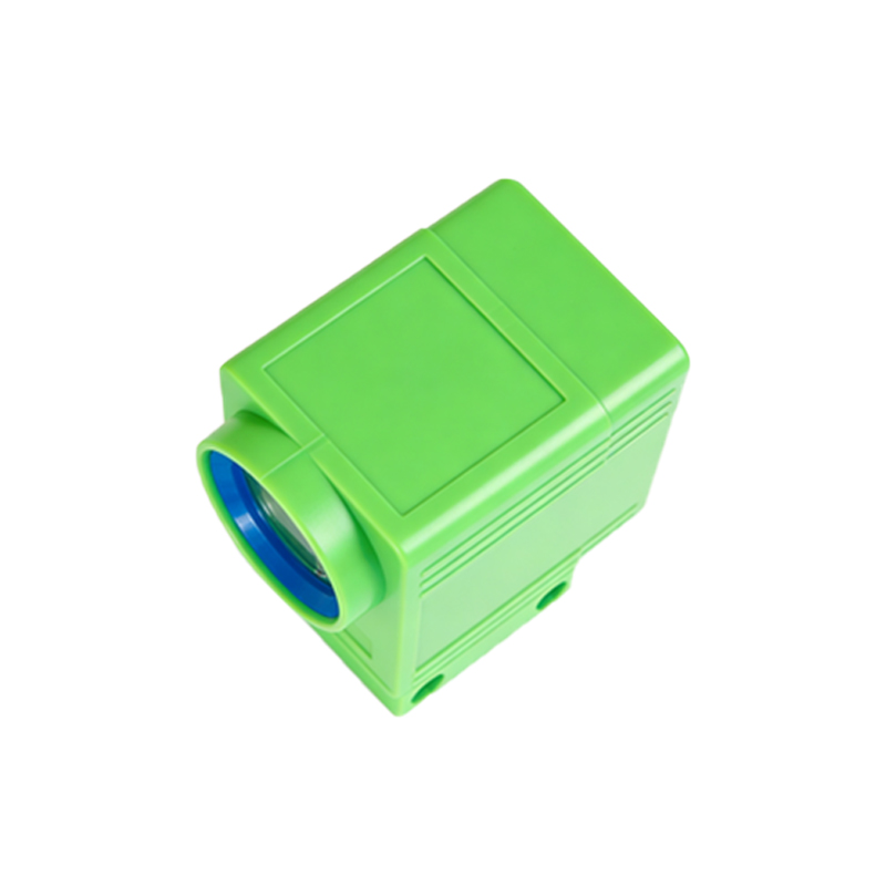
Working Principle and Common Types Used
Photoelectric sensors operate on a simple yet effective principle: they emit a beam of light (usually infrared or visible red) and detect changes in the received light signal. In the FA311, three main configurations are prevalent. Through-beam sensors consist of separate emitter and receiver units; an object is detected when it interrupts the light beam. This type is often used for critical break detection. Retro-reflective sensors use a single unit that emits light and receives its reflection from a dedicated reflector; they detect an object when it blocks this reflective path, commonly applied for can full detection. Diffuse reflective sensors detect the object itself by receiving light scattered back from its surface, suitable for detecting silver at various guide points. The choice depends on the required sensing distance, environmental challenges, and the specific detection task.
Critical Sensor Locations and Their Functions
Several strategic locations on the FA311 drawing frame are equipped with photoelectric sensors, each serving a vital purpose. The feed zone typically employs sensors to monitor the input silver from the creel, ensuring a continuous feed and initiating a stop if a silver breaks or runs out. Within the drafting system, sensors may be used to verify the silver path, preventing lapping around the rollers. The most crucial sensor is often found at the delivery section, monitoring the output silver for breaks. A break here triggers an immediate machine halt to prevent waste and potential damage. Another key set of sensors manages the automatic can changing cycle. They detect the fill level of the silver can and precisely position the empty can, ensuring a seamless transition without manual intervention, which is vital for uninterrupted production.
Common Failure Modes and Troubleshooting Steps
Despite their robustness, photoelectric sensors in the demanding environment of a drawing frame can encounter issues. The most common problem is contamination. Accumulation of lint, dust, or oil mist on the sensor's lens or reflector can attenuate the light signal, causing false triggers or failure to detect. Regular cleaning with appropriate tools is the first and most effective maintenance step. Misalignment is another frequent issue, especially for through-beam sensors, caused by vibration or accidental impact. Technicians must check and realign the emitter and receiver pairs. Electrical faults, such as loose connections, damaged cables, or voltage fluctuations, can also lead to sensor malfunction. A systematic approach using a multimeter to check power supply and output signals is essential. Finally, component aging can lead to diminished LED output or receiver sensitivity, necessitating sensor replacement.
Best Practices for Installation and Alignment
Proper installation is paramount for long-term sensor reliability. When installing a new or replacement sensor, ensure the mounting bracket is secure and free from vibration. For through-beam types, first roughly align the emitter and receiver by sight before powering the unit. Many modern sensors feature a built-in alignment aid, such as an LED indicator that changes color or brightness when optimal alignment is achieved. Use this feature meticulously. The sensing distance should be set with a margin; for instance, if the object is 100mm away, choose a sensor with a 150mm rated sensing distance to account for potential drift. Always consider the background environment; avoid placing reflective sensors where shiny surfaces or other light sources could cause interference. Securing all cabling away from moving parts prevents abrasion and disconnection.
Preventive Maintenance and Calibration Schedule
A proactive maintenance schedule drastically reduces unplanned stoppages. Daily, operators should perform a visual inspection for obvious contamination or physical damage. A weekly schedule should include a thorough cleaning of all sensor lenses and reflectors using compressed air and lint-free cloths, avoiding abrasive materials. Monthly, technicians should verify the alignment of critical sensors, especially those for can changing and silver break detection, using the machine's diagnostic menu or manual testing procedures. It is advisable to check the sensor's response time and signal stability annually as part of a comprehensive machine overhaul. Keeping a log of sensor failures and replacements helps identify patterns and potential root causes, such as a specific location prone to contamination or vibration.
Integration with Machine Control Systems
The photoelectric sensors are not isolated components; they are integral inputs to the FA311's Programmable Logic Controller (PLC). The PLC constantly scans the digital or analog signals from these sensors. A change in state, such as a light beam interruption, is processed by the control logic to execute a predefined action—stopping the drive motors, activating an alarm, or initiating the can changer. Understanding this integration is key for advanced troubleshooting. Technicians can often use the machine's human-machine interface (HMI) to monitor the real-time status of each sensor, which is invaluable for diagnosing intermittent faults. Replacing a sensor sometimes requires resetting a fault memory in the PLC or recalibrating parameters in the control software to ensure the new component's signal is correctly interpreted.
Upgrading to Modern Sensor Technologies
Older FA311 frames might be equipped with first-generation photoelectric sensors. Upgrading to contemporary models can offer significant benefits. Modern sensors feature improved ingress protection ratings (e.g., IP67), making them more resistant to dust and water splash. They often have brighter LEDs and more sensitive receivers, allowing for greater sensing distances or better performance in dirty conditions. Some advanced models include IO-Link communication, which provides detailed diagnostic data (like signal strength, temperature, contamination warnings) directly to the control system, enabling predictive maintenance. When considering an upgrade, compatibility with the existing voltage supply (e.g., 24V DC) and output type (PNP/NPN) must be confirmed. Retrofitting can enhance machine reliability and reduce the frequency of manual checks.