Understanding the Core Failure Mechanism
Inductive proximity sensors are workhorses in industrial automation, prized for their non-contact detection of metallic objects. However, a persistent and costly issue plaguing maintenance teams is the frequent burnout of these sensors. The core of the problem rarely lies with the sensor itself as a standalone component. Instead, burnout is almost always a symptom of external stress factors exceeding the sensor's designed electrical and thermal limits. The fundamental failure point is typically the sensor's internal oscillator circuit or output switching element (like a transistor). When subjected to excessive current, voltage spikes, or heat, these semiconductors degrade and ultimately fail in a short-circuit or open-circuit state, rendering the sensor inoperable. Recognizing that the burned sensor is the victim, not the culprit, is the first step toward a lasting solution.
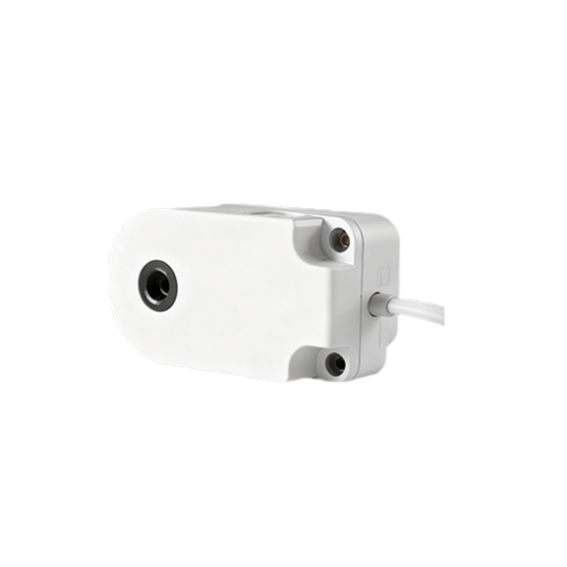
Overcurrent and Short-Circuit Scenarios
One of the most direct causes of burnout is excessive current flow through the sensor's output. This often occurs in three-wire DC sensors. If the load connected to the sensor's output (e.g., a PLC input, relay coil) draws more current than the sensor's rated switching capacity, the output transistor is forced to operate beyond its safe operating area. This generates excessive heat, leading to thermal runaway and destruction. A more severe instant failure happens when a direct short-circuit occurs at the load connection. Even with built-in short-circuit protection, many sensors cannot withstand a sustained short. Repeated inrush currents from inductive loads like solenoid valves or contactor coils are another silent killer, causing cumulative damage that weakens the output stage over time until it fails.
The Destructive Power of Voltage Transients and Surges
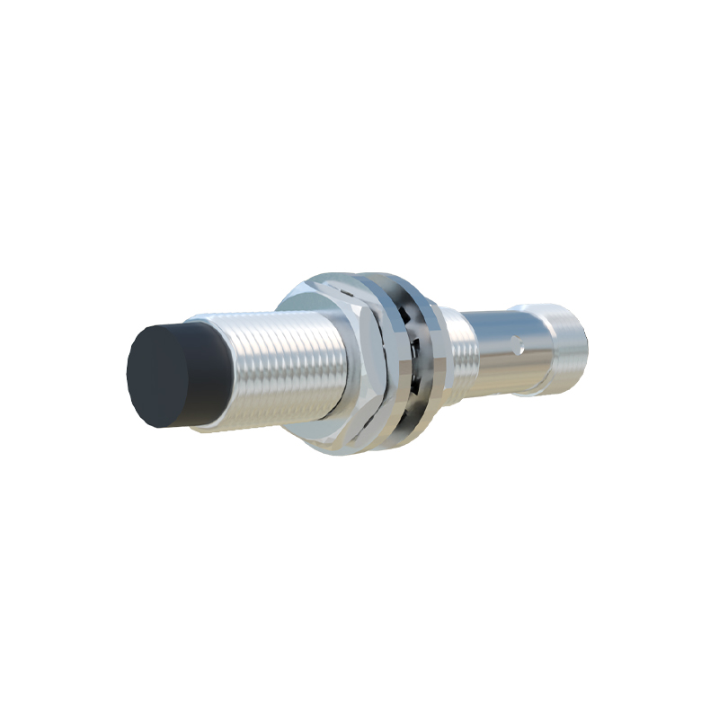
Industrial environments are electrically noisy. Voltage spikes and transients are primary assassins of inductive sensors. These surges can originate from multiple sources: the switching of large inductive loads elsewhere on the same power line (load dump), electrostatic discharge (ESD), or most commonly, from the relay or contactor coils the sensor itself is controlling. When the coil de-energizes, it generates a high-voltage flyback pulse. If this transient is not properly suppressed, it travels back into the sensor's output, easily exceeding the breakdown voltage of the semiconductor. While sensors have some internal protection, sustained or extremely high-energy transients will overwhelm it, causing an immediate or latent failure.
Incorrect Wiring and Power Supply Issues
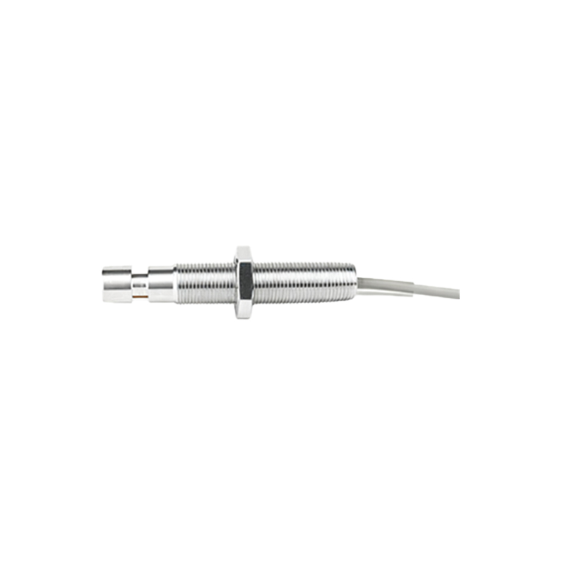
A significant percentage of sensor failures stem from basic wiring errors and unstable power. Connecting an AC sensor to a DC supply, or vice-versa, will cause immediate and catastrophic failure. Similarly, applying a voltage higher than the sensor's specified range (e.g., connecting a 12-24VDC sensor to a 48VDC line) will destroy it. Even with correct voltage, a poor-quality or overloaded power supply with excessive ripple and noise can stress the sensor's internal regulation circuitry. Ground loops, where the sensor and load are referenced to different ground potentials, can induce unexpected currents. Loose connections create arcing and intermittent operation, leading to thermal stress and eventual burnout.
Environmental Stress and Thermal Overload
Inductive sensors are designed for tough environments, but limits exist. Excessive ambient temperature is a major factor. Installing a sensor near a heat source like an oven, motor, or hydraulic line can cause its internal temperature to soar beyond its rated specification, often listed as 60-70°C for standard models. This heat reduces component lifespan and exacerbates heat generated internally by the output stage. Chemical exposure from coolants, oils, or solvents can degrade housing seals and, over time, damage internal electronics. Physical damage from vibration or impact can also cause internal shorts or broken connections that manifest as burnout.
Implementing Robust Preventive Solutions
Preventing burnout requires a systematic approach focused on the root causes. First, always ensure correct sensor selection: match the voltage type (AC/DC), voltage range, current rating (with a safety margin), and environmental rating (IP, temperature) to the application. For switching inductive loads, external suppression is non-negotiable. Use a flyback diode across DC coils or a Metal Oxide Varistor (MOV) for AC loads to clamp voltage transients. Always use a separate, regulated, and clean power supply for control circuits, isolating them from motor power lines. Install surge protection devices (SPDs) at the panel level. Ensure tight, correct wiring using ferrules and follow manufacturer diagrams precisely. Provide adequate spacing and cooling for sensors in hot environments, considering high-temperature rated models if necessary.
Diagnostic and Maintenance Best Practices
When a failure occurs, a thorough diagnosis prevents recurrence. Don't just replace the sensor