Understanding Proximity Sensor Fundamentals
Proximity sensors are indispensable components in modern industrial automation, providing non-contact detection of metallic or non-metallic objects. Their operation hinges on generating an electromagnetic field or beam of radiation. When a target enters this field, it causes a change in the signal, which the sensor converts into an electrical output. The core types include inductive (for metals), capacitive (for various materials including liquids), and photoelectric sensors. Selecting the correct sensor is the foundational step before any wiring commences, as the electrical characteristics and connection requirements differ significantly between types. A thorough review of the manufacturer's datasheet is non-negotiable, detailing the operating voltage, current consumption, output type (PNP/NPN, NO/NC), and housing material.
Essential Components and Pre-Wiring Checklist
A successful installation begins with gathering all necessary components and verifying system compatibility. The primary items include the proximity sensor itself, a suitable DC power supply (commonly 10-30V DC), the load device (e.g., a PLC input, relay coil, or indicator lamp), and the correct cabling. The pre-wiring checklist must confirm voltage compatibility between the sensor's supply and the power source. For three-wire sensors, which are most common, identify the brown wire (typically +V), the blue wire (typically 0V or common), and the black wire (switched output). For two-wire AC/DC sensors, confirm they are connected in series with the load. Always ensure power is completely disconnected and locked out (LOTO procedure) before handling any wires to prevent electrical shock or equipment damage.
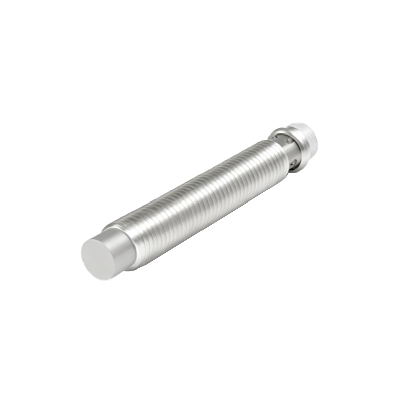
Standard Wiring Configurations: PNP vs. NPN
The most critical distinction in DC sensor wiring is between PNP (sourcing) and NNP (sinking) output types. This determines how the sensor interfaces with the control system's logic. A PNP sensor switches the positive voltage to the load. In a typical PNP wiring scheme, the brown wire connects to +V, the blue wire to 0V, and the black output wire connects to the load, which is then connected to 0V. When activated, the sensor sources current to the load. Conversely, an NPN sensor switches the negative or 0V line. Here, the brown wire connects to +V, the blue wire to 0V, and the black output wire connects to the load, which is then connected to +V. When activated, it sinks current from the load. Mismatching PNP and NPN with a PLC input is a common error that results in non-operation.
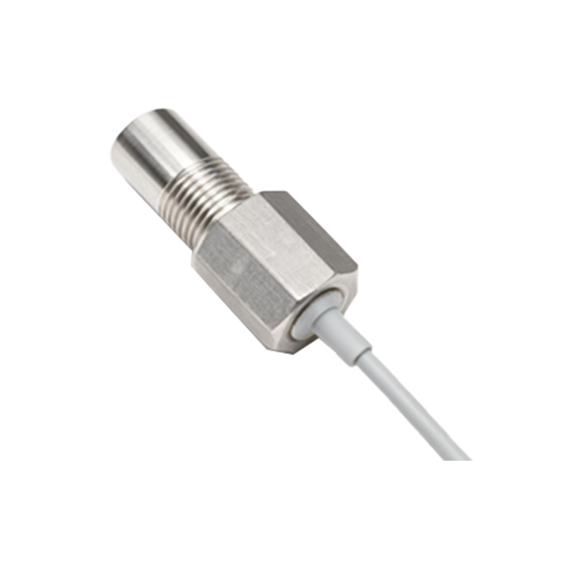
Step-by-Step Wiring Procedure
Following a systematic procedure ensures reliability and safety. First, permanently mount the sensor in its intended location, ensuring proper sensing distance and alignment. Route the sensor cable away from high-voltage power lines and motor drives to avoid electromagnetic interference. Strip the wire ends to the appropriate length. For a three-wire DC sensor: connect the brown wire to the positive terminal of your power supply. Connect the blue wire to the negative or 0V terminal of the supply. Connect the black output wire to one terminal of your load (e.g., PLC digital input). Finally, connect the other terminal of the load to the opposite power rail: to 0V for a PNP sensor or to +V for an NPN sensor. Secure all connections with appropriate terminals and ensure no loose strands are present.
Shielding, Grounding, and Noise Mitigation
Industrial environments are electrically noisy. Proper shielding and grounding are paramount for stable sensor operation. Always use shielded cables for sensor connections. Connect the cable's shield braid to a solid earth ground at the control panel end only, typically using a cable gland with an integrated shield clamp. Avoid grounding both ends, as this can create ground loops. Keep sensor wiring separate from high-current AC lines by at least several inches. If crossing is unavoidable, do so at a 90-degree angle. For highly noisy environments, consider using ferrite cores on the sensor cable near the connection points. A clean, dedicated ground point for all sensor commons in the panel is highly recommended to provide a stable reference potential.
Testing, Troubleshooting, and Maintenance
After wiring, apply power and systematically test the sensor. Use a non-metallic tool to bring a target into the sensing field. Observe the sensor's indicator LED (if present) and verify the expected state change at the load or PLC input. Common issues include no response, intermittent operation, or incorrect output state. A multimeter is essential for troubleshooting. Check for correct supply voltage at the sensor terminals. Verify the output voltage switches when the target is present/absent. For intermittent faults