Introduction to Photoelectric Sensors in Mechanical Meters
Photoelectric sensors are integral components in modern mechanical meters, enabling precise detection of rotational movement or position without physical contact. These sensors operate by emitting a light beam, typically from an LED, and detecting its reflection or interruption via a phototransistor or photodiode. In mechanical meters, such as water, gas, or electricity counters, they convert mechanical motion into electrical signals for monitoring and data logging. The wiring diagram for these sensors is crucial for ensuring accurate signal transmission and system reliability. Proper installation involves connecting power supply lines, output signals, and sometimes additional control wires, depending on the sensor type—whether diffuse, retro-reflective, or through-beam. Understanding the basic principles helps in configuring the wiring correctly to avoid errors like signal noise or voltage drops, which can lead to measurement inaccuracies.
Components of a Typical Photoelectric Sensor Wiring System
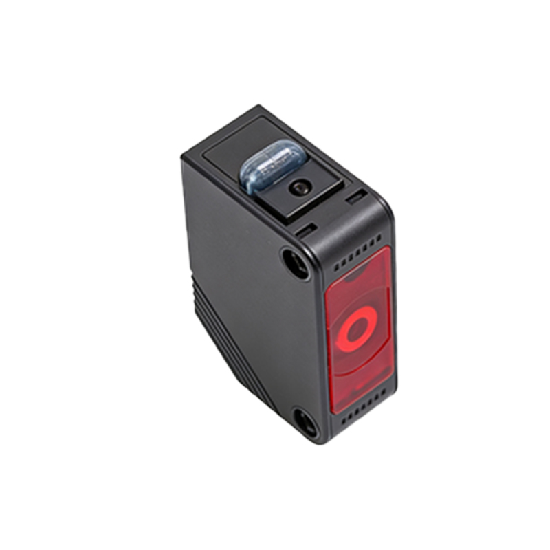
A standard photoelectric sensor wiring system for mechanical meters includes several key components. The sensor itself usually has three or four wires: a brown wire for positive DC voltage (often +12V to +24V), a blue wire for ground or negative connection, a black wire for the output signal (normally open or normally closed), and sometimes a white wire for additional functions like timer settings or complementary output. The power supply unit provides stable voltage to the sensor, while the load, such as a PLC (Programmable Logic Controller) or meter interface, receives the output signal. Protective elements like fuses or surge suppressors may be integrated to safeguard against electrical faults. The wiring diagram illustrates how these parts interconnect, specifying terminal points and cable types—typically shielded cables to minimize electromagnetic interference. It's essential to match wire colors with manufacturer guidelines, as variations can occur between brands.
Step-by-Step Wiring Diagram Explanation
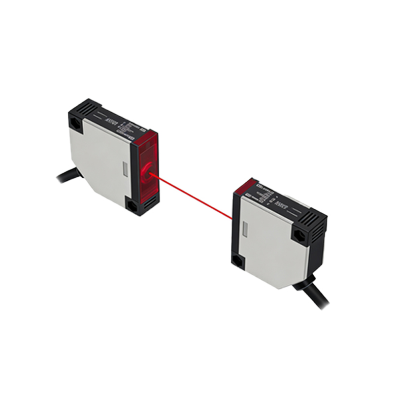
To wire a photoelectric sensor to a mechanical meter, start by reviewing the manufacturer's datasheet for voltage ratings and pin configurations. First, connect the brown wire from the sensor to the positive terminal of the DC power supply, ensuring the voltage matches the sensor's specification (e.g., 12V DC). Next, attach the blue wire to the negative terminal or ground of the power supply. Then, link the black output wire to the input terminal of the meter or control device; if using a normally closed configuration, verify the circuit logic to avoid reverse signals. If a white wire is present, consult the manual for its purpose—it might connect to an auxiliary control line. Use crimp connectors or terminal blocks for secure joints, and avoid loose wiring that could cause intermittent faults. The diagram should show clear paths, with labels for each connection point and notes on cable lengths, typically kept short to reduce resistance. Test the setup with a multimeter to confirm continuity and correct voltage levels before powering the system fully.
Common Wiring Configurations and Their Applications
Photoelectric sensors in mechanical meters can be wired in various configurations based on application needs. The two-wire configuration is simple, combining power and output in a single loop, but it may have limitations in current handling. The three-wire setup is most common, with separate lines for power and output, offering better stability for precise meter readings—ideal for detecting gear teeth or dial rotations in counters. Four-wire sensors provide enhanced functionality, such as programmable outputs or dual channels, useful in complex metering systems requiring multiple detection points. For instance, in a water meter, a through-beam sensor might be wired to monitor flow by interrupting light across a paddle wheel, with the diagram showing emitter and receiver units connected to separate power sources. Always refer to application notes to choose the right configuration, considering factors like environmental conditions (e.g., dust or moisture) that might affect sensor performance and wiring durability.
Troubleshooting and Best Practices for Wiring
When issues arise with photoelectric sensor wiring in mechanical meters, systematic troubleshooting is key. Check for loose connections or corroded terminals first, as these can disrupt signal flow. Use a voltmeter to measure voltage at the sensor terminals; if it's below the specified range, inspect the power supply and wiring for drops. Ensure the sensor alignment is correct—misalignment can cause false triggers, mimicking wiring faults. For noise interference, verify that shielded cables are properly grounded and kept away from high-voltage lines. In the wiring diagram, include notes on recommended cable types (e.g., twisted pairs for noise reduction) and separation distances from other equipment. Best practices involve labeling all wires during installation, using color-coded tapes if original colors fade, and following industry standards like IEC 60947 for electrical safety. Regular maintenance, such as cleaning sensor lenses and tightening connections, prolongs system life and ensures accurate meter operation. Document any changes to the wiring diagram for future reference, aiding in quick repairs or upgrades.