Introduction to 3-Wire Proximity Sensor Wiring
Proximity sensors are fundamental components in modern industrial automation, providing non-contact detection of metallic or non-metallic objects. Among the various configurations, the 3-wire DC sensor is the most prevalent in factory settings. Its wiring scheme is deceptively simple yet critical for reliable operation. Unlike 2-wire sensors that are wired in series with the load, 3-wire sensors require a separate power supply, offering distinct advantages in switching speed, leakage current, and diagnostic capabilities. The three wires are universally color-coded or labeled: brown for the positive supply voltage (V+), blue for the negative supply or common (0V), and black for the switched output signal. It is the function and proper handling of the common wire, typically the blue wire, that forms the core of a robust sensor installation.
The Critical Role of the Common Wire (Blue Wire)
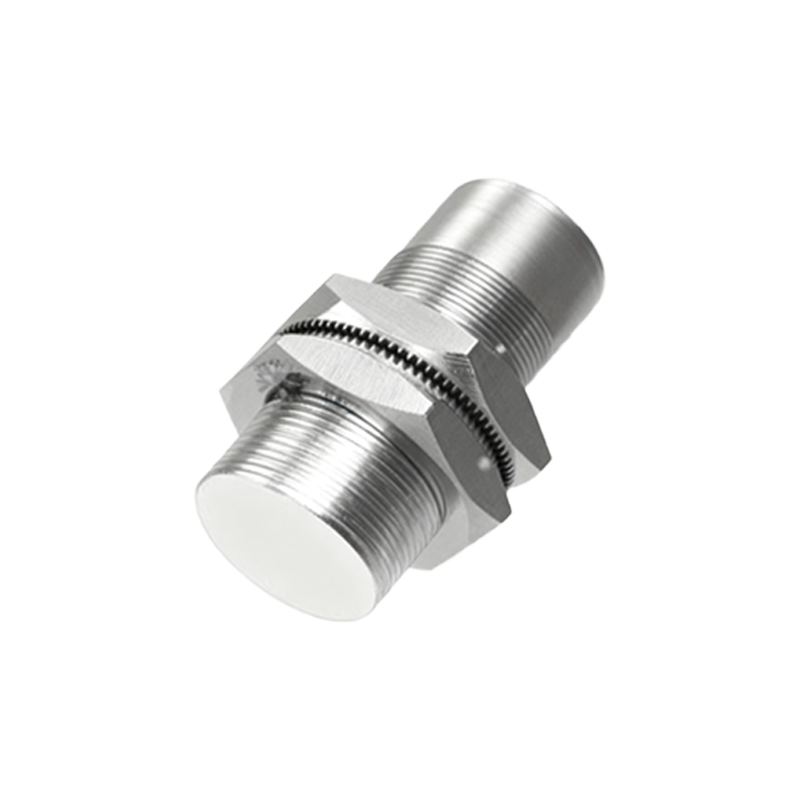
The common wire, most often the blue conductor, serves as the electrical reference point for the entire sensor circuit. It is the return path to the power supply for both the sensor's internal electronics and, crucially, for the output switching element. In a standard NPN (sinking) sensor, the black output wire switches the load by connecting it to the common (0V) when active. Conversely, in a PNP (sourcing) sensor, the black output wire switches the load by connecting it to the positive supply (V+) when active, but the common remains the essential return path for the sensor's internal circuitry. Therefore, the common is not merely a neutral wire; it is the foundational ground reference. A poor connection at this point can lead to erratic sensor behavior, voltage fluctuations, and even damage to connected controllers like PLCs.
Wiring Configurations: NPN vs. PNP and the Common
Understanding the common wire's role is inseparable from knowing the sensor's output type. For an NPN sensor, the output transistor connects the load to the common (0V). Here, the load (e.g., a PLC input) is connected between the positive supply and the sensor's black wire. When the sensor activates, it "sinks" current from the load down to the common. For a PNP sensor, the output transistor connects the load to the positive supply (V+). The load is connected between the sensor's black wire and the common. When active, it "sources" current from the supply, through the load, to the common. In both cases, the blue common wire must be securely connected to the power supply's 0V terminal. A critical rule is never to intermix NPN and PNP sensors on the same common circuit without isolation, as this can create short circuits.
Practical Installation and Troubleshooting Tips
Correct installation begins with verifying the sensor's specifications. Always connect the brown wire to DC positive (typically +12V or +24V) and the blue wire to DC negative/0V. The black wire goes to the input of your controller. Ensure all connections are tight and use ferrules on stranded wire to prevent stray strands. The most common issue related to the common wire is "common ground loops" or potential differences. If the sensor's common (blue wire) is connected to a different 0V point than the PLC's common, a voltage difference may exist, causing false triggering or sensor failure. Always use a single, star-point grounding scheme for the entire system. Use a multimeter to check for continuity between the sensor's blue wire terminal and the PLC's common terminal; resistance should be near zero ohms.
Interfacing with PLCs and Control Systems
When connecting to a Programmable Logic Controller (PLC), the treatment of the common wire is paramount. Most PLC digital input cards are designed for either sinking (NPN) or sourcing (PNP) inputs, which dictates the sensor type you must use. The PLC's input card itself will have a common terminal, often labeled "COM" or "M". For a system using NPN sensors, the PLC's common for the input group is usually connected to the positive supply (+24V), and each input is connected to the sensor's black wire. The sensor's blue wire is connected to the power supply's 0V. This completes the circuit. The key is ensuring the sensor's common (0V) and the PLC's power supply common are at the exact same potential, often achieved by connecting them to the same robust busbar or terminal block.
Advanced Considerations: Shielded Cables and Noise Immunity
In electrically noisy environments, such as those with variable frequency