Introduction to Q12 Photoelectric Sensor
The Q12 series represents a versatile line of photoelectric sensors designed for robust industrial automation applications. These sensors utilize advanced optical technology to detect the presence, absence, or distance of objects with high precision and reliability. Engineered for durability, the Q12 sensors are housed in a compact, rugged casing that provides excellent resistance to environmental factors such as dust, moisture, and mechanical vibration. They are integral components in conveyor systems, packaging machinery, material handling, and assembly lines, offering a critical solution for non-contact detection needs. Their design emphasizes ease of installation, consistent performance, and long-term operational stability, making them a preferred choice for engineers seeking to enhance system efficiency and automation accuracy.
Key Technical Specifications and Operating Principles
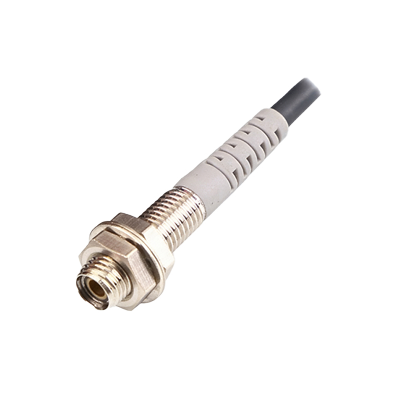
Operating on the principle of modulated infrared light, the Q12 sensor emits a light beam from its transmitter. The receiver then detects the presence or interruption of this beam. Key specifications include a sensing range of up to 15 meters for the through-beam models, with a response time of less than 1 millisecond, ensuring rapid detection for high-speed applications. The sensors typically operate on a supply voltage range of 10-30 VDC, with both NPN and PNP output configurations available to interface seamlessly with various PLCs and control systems. They feature a high IP67 protection rating, ensuring reliable performance in harsh industrial environments. The operating principle allows for multiple detection modes: through-beam, retro-reflective, and diffuse reflective, each suited for specific application scenarios requiring different levels of precision and environmental considerations.
Installation Guidelines and Mounting Procedures
Proper installation is crucial for optimal sensor performance. Begin by selecting a stable mounting location free from excessive vibration and direct exposure to strong ambient light, which could cause interference. Ensure the sensor is securely fastened using the provided brackets or mounting hardware. For through-beam types, precisely align the transmitter and receiver units to ensure the light beam path is unobstructed. The alignment indicators, often LED-based, provide visual confirmation of correct positioning. Maintain the recommended sensing distance as per the model's datasheet, and avoid placing reflective surfaces near the detection field for diffuse sensors. Always disconnect power during installation and verify all electrical connections are tight and correct according to the wiring diagram provided in the manual.
Wiring Configuration and Electrical Connections
The Q12 sensor features a standard 4-pin M12 connector or cable outlet for simplified wiring. The typical pinout includes connections for power supply (brown wire for +V, blue wire for 0V), output signal (black wire), and a diagnostic or teach-in function wire (white wire, if available). Connect the power leads to a stable DC power source within the specified voltage range. The output wire should be connected to the input module of your controller (PLC). It is imperative to observe correct polarity and to implement necessary protective measures, such as fuses or surge protectors, in the circuit. For sensors with programmable functions, follow the specific sequence outlined in the manual to set parameters via the teach-in button or external control inputs.
Configuration, Calibration, and Adjustment Methods
Many Q12 models offer adjustable sensitivity and response time to fine-tune performance for specific applications. Use the potentiometer or push-button interface to set the detection threshold, minimizing false triggers from background objects or environmental noise. For precise distance setting in diffuse sensors, utilize the teach-in function by presenting the target object at the desired detection distance and activating the programming mode. Calibration should be performed under actual operating conditions. Regularly verify the sensor's alignment and output signal using the built-in stability indicator LED. Some advanced models may support IO-Link communication for digital parameterization and diagnostics directly from a central control system.
Diagnostic Indicators and Troubleshooting Common Issues
The Q12 is equipped with a multi-color LED status indicator. A steady green light typically signifies power-on and normal operation, while a flashing green or amber light may indicate object detection, alignment status, or a warning condition. A red LED often signals a fault, such as a wiring error, short circuit, or contamination on the lens. Common issues include failure to detect objects, intermittent operation, or unstable output. First, check for physical obstructions, lens cleanliness, and secure electrical connections. Verify the power supply voltage and ensure the sensing range and mode are correctly configured for the target object's properties. Consult the troubleshooting chart in the manual for systematic fault isolation.
Maintenance, Cleaning, and Operational Best Practices
To ensure long-term reliability, implement a routine maintenance schedule. Periodically clean the sensor lens with a soft, lint-free cloth to remove dust, oil, or debris that could attenuate the light signal. Avoid using abrasive or chemical cleaners. Inspect the housing for any physical damage and ensure all seals are intact to maintain the IP rating. Regularly test the sensor's response with a standard test object. Operate the sensor within its specified temperature, humidity, and environmental limits. Keeping a log of performance checks can help in predictive maintenance. Always refer to the manufacturer's guidelines for any specific maintenance procedures or recommended spare parts.
Application Examples and Industry Use Cases
The Q12 photoelectric sensor finds extensive application across various industries. In automotive manufacturing, it is used for part presence verification on assembly robots. In packaging, it detects labels, counts products on high-speed fillers, and monitors fill levels. In logistics, it ensures parcel positioning on sorting conveyors. Its robust design makes it suitable for outdoor applications like vehicle detection in access control systems. The sensor's high-speed response is critical in electronics assembly for PCB board positioning. By selecting the appropriate detection mode and configuring it correctly, engineers can solve complex automation challenges, improving throughput, safety, and quality control in diverse operational environments.