Introduction to Proximity Sensor Wiring
Proximity sensors are fundamental components in industrial automation, detecting the presence or absence of objects without physical contact. Among various configurations, the 3-wire proximity sensor is the most prevalent in modern control systems. Unlike 2-wire sensors that are wired in series with the load, 3-wire sensors provide separate paths for power supply, ground, and the switching signal. This design offers superior performance, reliability, and diagnostic capabilities. Typically operating on DC voltage (commonly 12-24V DC), these sensors consist of three distinct wires: a brown wire for positive supply voltage (+V), a blue wire for the common ground (0V), and a black wire that serves as the output signal line. The output can be either NPN (sinking) or PNP (sourcing), determining how the load is connected in the circuit. Understanding this wiring is crucial for correct integration into Programmable Logic Controller (PLC) systems, relay modules, and other control devices.
Core Components and Electrical Characteristics
The internal circuitry of a 3-wire inductive or capacitive proximity sensor is designed for stability. The brown wire connects to the positive terminal of the DC power source, energizing the sensor's oscillator and amplifier circuits. The blue wire completes the circuit by connecting to the power supply's negative terminal. The critical third wire, black, is the switched output. In a PNP configuration, the black wire sources current from the sensor's internal switch to the load when a target is detected. Conversely, in an NPN configuration, the black wire sinks current from the load to ground upon detection. Key electrical specifications include the operating voltage range (e.g., 10-30V DC), output current capacity (often 200mA), and leakage current (minimal when off). This design minimizes voltage drop across the sensor, ensuring a crisp, full-voltage signal to the load, which is essential for high-speed counting or precise positioning applications.
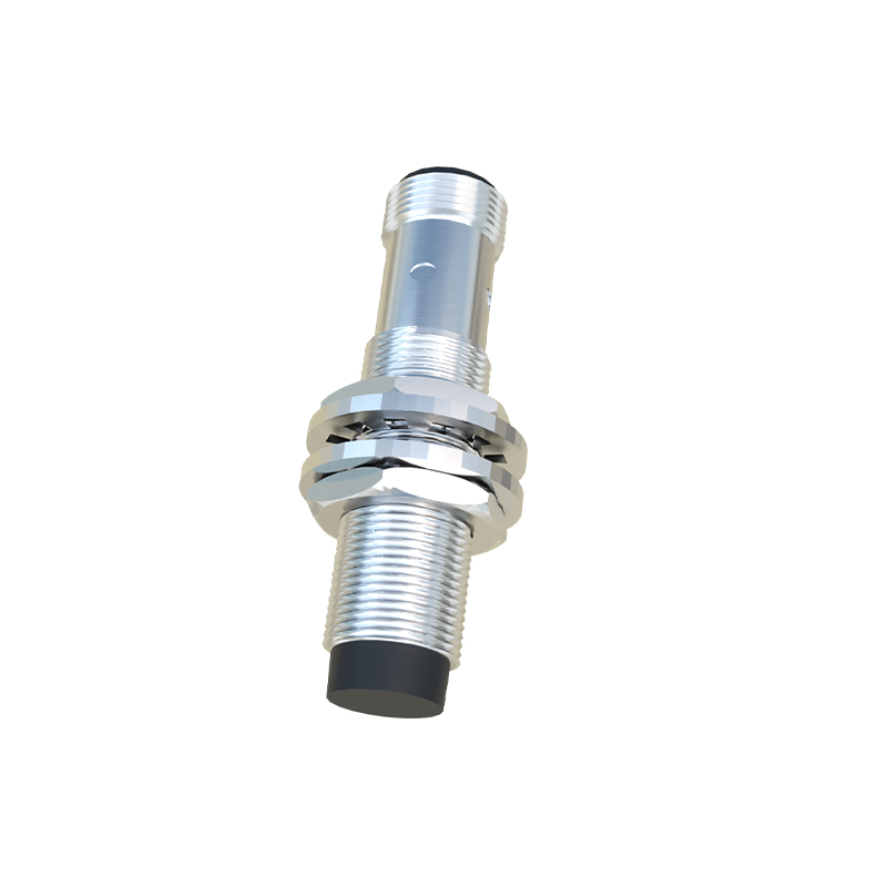
NPN vs. PNP Output Types Explained
Selecting between NPN and PNP output is a critical decision in system design, primarily dictated by the input module of the controller. A PNP (Positive-Positive-Negative) sensor, also known as a "sourcing" sensor, switches the positive voltage to the load. Its output wire (black) goes high (to +V) when activated. This type is commonly used with PLCs that have sinking input modules, prevalent in European and many global standards. An NPN (Negative-Positive-Negative) sensor, or a "sinking" sensor, switches the ground connection. Its output wire goes low (to 0V) when activated, completing the circuit to ground. NPN sensors are often paired with sourcing PLC input modules, frequently found in Asian and some North American applications. Miswiring these types can lead to system malfunctions or damage. Always verify the controller's input specifications and the sensor's datasheet before installation.
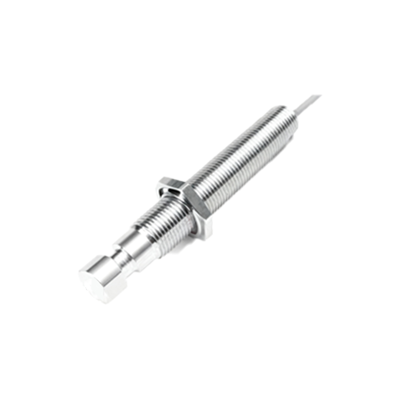
Installation, Wiring Practices, and Diagnostics
Proper installation is paramount for reliable operation. First, ensure the power is disconnected. Connect the brown wire to the positive DC supply and the blue wire to the negative. The black output wire is then connected to the input channel of the PLC, relay, or indicator. For an NPN sensor, the load must be connected between the positive supply and the black wire. For a PNP sensor, the load is connected between the black wire and ground. Use shielded cables in electrically noisy environments, grounding the shield at one end only. Maintain adequate clearance from high-voltage power lines and motors to avoid electromagnetic interference. For diagnostics, a simple multimeter can check for supply voltage at the brown-blue terminals. When a target is presented, the voltage between the black and blue wires should switch from ~0V to near supply voltage (for PNP) or vice-versa (for NPN). Consistent failure may indicate incorrect wiring, insufficient voltage, or a damaged sensor.
Advantages Over 2-Wire and 4-Wire Sensors
The 3-wire design strikes an optimal balance between functionality and cost. Compared to 2-wire sensors, which are essentially electronic switches in series with the load, 3-wire sensors offer significantly lower leakage current (ensuring the load turns off completely), higher switching speeds, and better immunity to voltage fluctuations. They also allow for direct connection to most solid-state PLC inputs without needing an external relay. In contrast to 4-wire sensors, which often provide both a Normally Open (NO) and a Normally Closed (NC) output, the 3-wire version is