Introduction to Valve Photoelectric Sensors
Valve photoelectric sensors are critical components in modern industrial automation, providing non-contact detection for valve position, status, and control. These sensors utilize light beams, typically infrared or visible light, to detect the presence, absence, or position of a valve component, such as a spool, actuator, or flag. The core principle involves an emitter that projects a light beam and a receiver that detects the beam's interruption or reflection. In valve applications, this allows for precise monitoring of open/closed states, stroke end positions, or intermediate positions in proportional valves. The reliability of these sensors is paramount, as they directly influence system safety, efficiency, and diagnostic capabilities. Engineers rely on clear, detailed images of these sensors for selection, integration, troubleshooting, and maintenance purposes. High-quality technical images provide insights into form factor, mounting styles, connection types, and sensing modes, which are essential for ensuring compatibility with specific valve types and harsh industrial environments.
Key Components Visible in Sensor Images
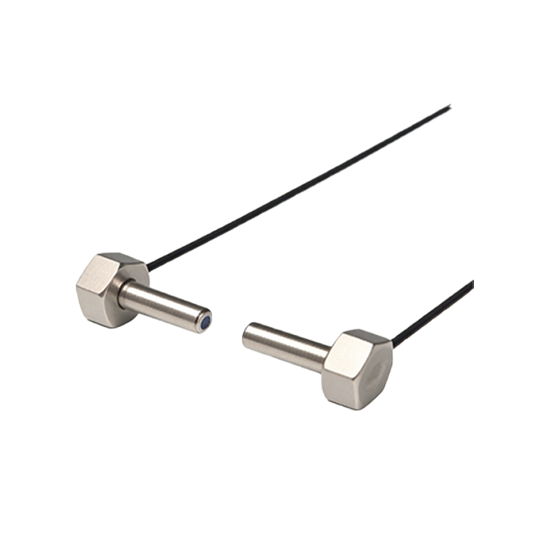
Analyzing a standard valve photoelectric sensor image reveals several key physical and functional components. The housing, often constructed from rugged materials like nickel-plated brass, stainless steel, or PBT plastic, is designed to withstand industrial conditions, including moisture, vibration, and chemical exposure. The lens or optical window is a critical feature, protecting the internal emitter and receiver. Images clearly show the sensing face, which may be configured for through-beam, retro-reflective, or diffuse reflection modes. For through-beam types, images depict separate emitter and receiver units. Electrical connections, such as M8, M12 connectors, or cable outlets with specific pin assignments (e.g., PNP/NPN), are prominently visible. Many modern sensors incorporate LED indicators for power and output status, which are clearly shown in images to aid in visual diagnostics. Mounting accessories, like adjustable brackets or specific valve-adaptor kits, are often featured in application photos, demonstrating how the sensor interfaces physically with different valve bodies from manufacturers like Festo, SMC, or Parker.
Interpreting Sensing Modes from Visual Cues
The physical design captured in an image directly indicates the sensor's operating mode. Through-beam sensor images show two separate, opposing housings that must be aligned. This mode offers the longest sensing range and highest reliability for detecting valve flags or targets. Retro-reflective sensor images display a single housing with both emitter and receiver, designed to work with a reflector. This is common for detecting the presence of a valve actuator at a distance. Diffuse reflective (proximity) sensors have a compact, single housing and detect the reflection from the target itself, such as a valve spool or piston end. Advanced images may depict background suppression or fixed-field versions, which are crucial for ignoring irrelevant surfaces near the valve. For valve position feedback, images often show sensors with built-in potentiometers or DIP switches for sensitivity adjustment, visible as small dials or access slots on the housing. These visual details help engineers select the correct sensor to avoid false triggers from shiny metal valve surfaces or to ensure detection of small, fast-moving targets.
Application-Specific Images and Installations
Contextual application images are invaluable. They show photoelectric sensors installed on pneumatic cylinders, rotary actuators, ball valves, and butterfly valves. For instance, an image might show a compact sensor mounted on the end position of a pneumatic cylinder to confirm piston extension or retraction, with the sensing target being the piston rod's magnetic or non-magnetic collar. Another common image depicts a sensor array along a linear actuator's path for multi-position feedback. For process valves, images illustrate how sensors are mounted on valve stems or actuators to indicate open/closed status to a control system like a PLC. These photos highlight environmental challenges: sensors in washdown areas for food & beverage have IP69K ratings, visible as smooth, sealed housings; those in explosive atmospheres have ATEX/IECEx markings on the label, shown in close-up shots. Installation images also demonstrate proper alignment, cable routing, and the use of protective shrouds to prevent mechanical damage from moving valve linkages.
The Role of Images in Troubleshooting and Selection
Technical diagrams and real-world problem images are essential tools. Cross-sectional diagrams reveal internal optics and electronics, explaining sensing characteristics. Comparison images help distinguish between similar models, such as short-body vs. long-body sensors for tight mounting spaces on valve manifolds. Troubleshooting images might show a sensor with a scratched lens causing erratic signals, misalignment due to vibration loosening a bracket, or condensation inside the housing in cold environments. For selection, dimensional drawings with precise measurements (in millimeters and inches) are critical for integration into valve assembly designs. Images of output signal timing diagrams, often superimposed on product photos, explain the switching logic (light-on/dark-on) relevant to PLC programming. Furthermore, images displaying international certification marks (UL, CE, RoHS) on the sensor body provide immediate verification of compliance for global projects. Engineers use these visual resources to preempt installation issues and ensure the sensor's optical and mechanical specifications match the valve's operational profile.
Future Trends and Imaging Technology
Advancements in sensor and imaging technology are converging. High-resolution product images now often include QR codes that link to 3D models, datasheets, or configuration software. The sensors themselves are becoming more intelligent, with built-in IO-Link capability, visible as an additional communication pin or a specific logo on the housing. Images of these smart sensors show them providing digital parameterization and diagnostic data (like lens contamination warnings) directly to valve controllers. Furthermore, augmented reality (AR) is emerging as a tool; engineers can use AR applications to overlay a photoelectric sensor's virtual image onto a real valve assembly to visualize fit and cabling before purchase. Photographic standards are also improving, with manufacturers providing ISO-compliant technical illustrations that show exact light beam dispersion angles and sensing fields superimposed on the valve target, removing guesswork from application engineering. This visual clarity supports the trend towards faster, more reliable automated valve systems in Industry 4.0 and smart factory environments.