Introduction to Proximity Sensor Wiring
Proximity sensors are fundamental components in modern industrial automation, providing non-contact detection of metallic or non-metallic objects. Understanding their wiring is crucial for correct installation, reliable operation, and effective troubleshooting. These sensors typically come in three main types: inductive (for metals), capacitive (for various materials including liquids), and photoelectric (using light beams). Despite their operational differences, the wiring principles for standard DC 3-wire and 4-wire sensors share common conventions. This guide provides a detailed explanation of common proximity sensor wiring diagrams, focusing on the widely used 3-wire DC configuration, to empower engineers and technicians with practical knowledge for field applications.
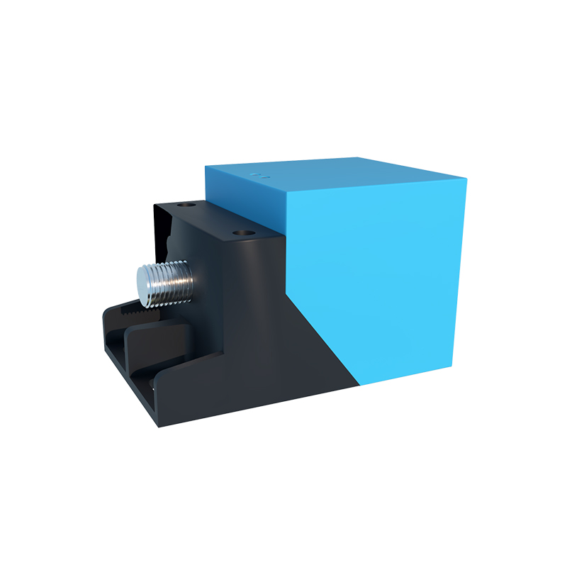
Standard 3-Wire DC Sensor Configuration
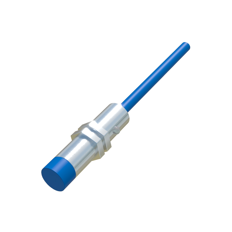
The 3-wire DC proximity sensor is the industry workhorse. Its wiring involves three distinct conductors, usually color-coded as brown, blue, and black. The brown wire is universally designated for the positive DC supply voltage, typically ranging from 10 to 30 VDC. The blue wire is always connected to the DC common or negative (0V) terminal of the power supply. The critical third wire, most often black, is the signal output line. The function of this black wire defines the sensor's output type: a PNP (sourcing) sensor switches the positive voltage to the load, while an NPN (sinking) sensor switches the negative or ground path. Correctly identifying whether you have a PNP or NPN sensor is the first and most vital step before making any connections to a PLC input module or relay.
Detailed PNP (Sourcing) Wiring Diagram
A PNP proximity sensor sources current to the load. In a typical wiring diagram, the brown wire connects to the positive terminal of the DC power supply. The blue wire connects to the negative terminal. The black output wire is connected to one terminal of the load (e.g., a PLC digital input). The other terminal of the load is then connected back to the DC common (blue wire/negative). When the sensor detects a target, it internally connects the black wire to the positive supply (brown wire), completing the circuit and "sourcing" positive current through the load to common. This energizes the load. The load, therefore, receives power from the sensor's output. It is essential to note that for a PNP sensor, the PLC input module must be configured to accept a sourcing signal, meaning its common point is connected to negative.
Detailed NPN (Sinking) Wiring Diagram
Conversely, an NPN proximity sensor sinks current from the load. The power connections remain identical: brown to positive, blue to negative. The difference lies in the output. The black output wire is connected to the DC common (negative). One side of the load is connected to the positive supply. The other side of the load is connected to the sensor's output terminal (often still a black wire, but functioning as a switch to negative). When activated, the NPN sensor internally connects the black wire to the negative supply (blue wire), providing a path to ground and "sinking" current from the load through the sensor. This completes the circuit and energizes the load. For an NPN sensor, the connected PLC input must be of the sinking type, with its common point connected to positive.
Wiring for 4-Wire DC Sensors and NO/NC Contacts
Four-wire DC sensors provide both a Normally Open (NO) and a Normally Closed (NC) output from a single device. They have the standard brown (positive) and blue (negative) wires, plus two output wires, commonly black and white. One wire is for the NO contact, and the other is for the NC contact. The wiring diagram follows the same PNP/NPN logic for each output. For a PNP 4-wire sensor, both black and white wires would source positive voltage when active (depending on their NO/NC state). The key is to consult the sensor's datasheet to identify which color corresponds to which contact type. This configuration offers flexibility in control logic without needing an external relay to invert the signal.
Connecting to PLCs and Load Considerations
Integrating proximity sensors with Programmable Logic Controllers (PLCs) requires attention to compatibility. Always match the sensor's output type (PNP/NPN) with the PLC input card's specification. Mismatching can lead to non-operation or potential damage. Most modern PLC input modules are configurable or designed to accept both types. A crucial element often included in the wiring diagram is a protective device. A fast-blow fuse, typically rated just above the sensor's operating current, should be