Introduction to Proximity Switch Sensors
Proximity switch sensors are indispensable components in modern injection molding machinery, serving as non-contact detection devices that ensure precise and reliable operation. These sensors detect the presence or absence of metallic objects without physical contact, utilizing electromagnetic fields or capacitive principles. In the high-speed, automated environment of injection molding, they play a critical role in monitoring mold position, ejector plate movement, safety door status, and part ejection. Their ability to function in harsh conditions—resisting oil, dust, and mechanical vibration—makes them ideal for the demanding plastic processing industry. The selection and application of these sensors directly impact machine efficiency, product quality, and operational safety.
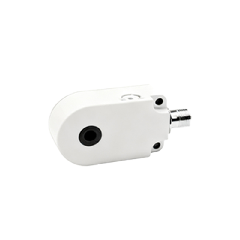
Types of Proximity Sensors Used
Two primary types of proximity sensors are prevalent in injection molding applications: inductive and capacitive. Inductive proximity sensors are the most common, designed to detect ferrous and non-ferrous metals. They generate an oscillating electromagnetic field; when a metal target enters this field, it induces eddy currents, causing the sensor to switch. These are typically used for detecting mold clamps, cylinder positions, or metal inserts. Capacitive proximity sensors, on the other hand, can detect both metallic and non-metallic materials, such as plastics or liquids, by measuring changes in capacitance. This makes them suitable for applications like monitoring plastic pellet levels in hoppers or detecting non-metallic parts during ejection. Each type offers specific advantages in terms of sensing range, response time, and environmental resistance.
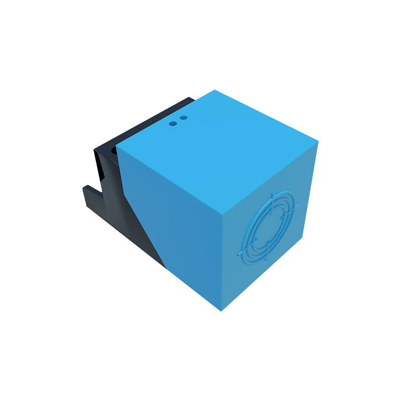
Key Application Points in Injection Molding
In injection molding machines, proximity sensors are strategically installed at multiple points to automate and safeguard the process. A crucial application is mold safety monitoring, where sensors verify that the mold is fully closed before injection begins, preventing damage and ensuring operator safety. They are also employed on ejector systems to confirm that molded parts have been successfully ejected, signaling the machine to proceed to the next cycle. Additionally, sensors monitor the position of the screw and injection unit, ensuring accurate metering and injection phases. On the clamping unit, they detect the position of the moving platen, enabling precise control over mold opening and closing speeds. Proper installation—considering factors like sensing distance, target material, and alignment—is essential to avoid false triggers and ensure longevity.
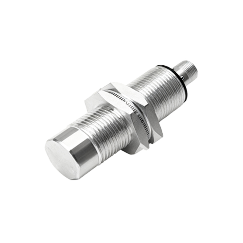
Installation and Alignment Best Practices
Correct installation is paramount for optimal sensor performance. Sensors should be mounted securely to minimize vibration-induced errors, with adequate clearance from other metal parts to prevent interference. The sensing face must be aligned parallel to the target surface, maintaining the specified nominal sensing distance. For inductive sensors, it is important to account for the reduction factor when detecting non-ferrous metals, which may require a shorter effective range. Wiring should follow manufacturer guidelines, using shielded cables in electrically noisy environments to prevent signal disruption. Regular maintenance, including cleaning the sensor face from oil or debris buildup, ensures consistent detection. Many modern sensors feature LED indicators for easy diagnostics, helping technicians quickly identify issues like misalignment or wiring faults.
Common Challenges and Troubleshooting
Despite their robustness, proximity sensors can face challenges in injection molding settings. Contamination by mold release agents, grease, or plastic particles may coat the sensor face, attenuating the sensing signal and causing failures. High ambient temperatures near the mold can exceed sensor specifications, leading to drift or permanent damage. Electrical interference from motors or heaters might induce false switching. To troubleshoot, first inspect the sensor and target for physical obstructions or misalignment. Verify the power supply and check wiring connections for corrosion or breaks. Using a multimeter, measure the output signal to confirm switching operation. If intermittent faults occur, consider upgrading to sensors with higher ingress protection (IP) ratings or enhanced noise immunity. Implementing preventive maintenance schedules can mitigate many of these issues.
Advancements and Future Trends
Technological advancements are continuously enhancing proximity sensor capabilities in injection molding. Smart sensors with IO-Link communication provide real-time diagnostic data, such as operating temperature, switch cycles, and signal strength, enabling predictive maintenance and reducing downtime. Miniaturized sensors allow installation in tight spaces without compromising performance. There is also a growing trend toward using analog output sensors for position feedback, offering more granular control over machine movements. Furthermore, sensors with extended temperature ranges and improved chemical resistance are being developed to withstand increasingly harsh processing environments. As Industry 4.0 integrates deeper into manufacturing, these sensors will play a pivotal role in data collection and process optimization, contributing to smarter, more efficient injection molding operations.
Conclusion and Selection Guidelines
Selecting the right proximity sensor for an injection molding machine requires careful consideration of application requirements. Key factors include the target