Understanding Reflective Photoelectric Sensor Operation
Reflective photoelectric sensors are fundamental components in industrial automation, packaging, and material handling. They operate on a simple yet effective principle: an internal light emitter, typically an LED, projects a beam of light towards a target. A phototransistor or photodiode receiver, positioned adjacent to the emitter, detects the light that is reflected back from the target. The sensor's output state changes based on the intensity of this received light. For diffuse reflective sensors, the target itself acts as the reflector. For retro-reflective types, a dedicated reflector is used, and the sensor detects the interruption of the beam. Understanding this basic "emit and receive" mechanism is the first step in diagnosing performance issues. A failure in either the emitting or receiving component, or in the signal processing circuitry, will lead to sensor malfunction.
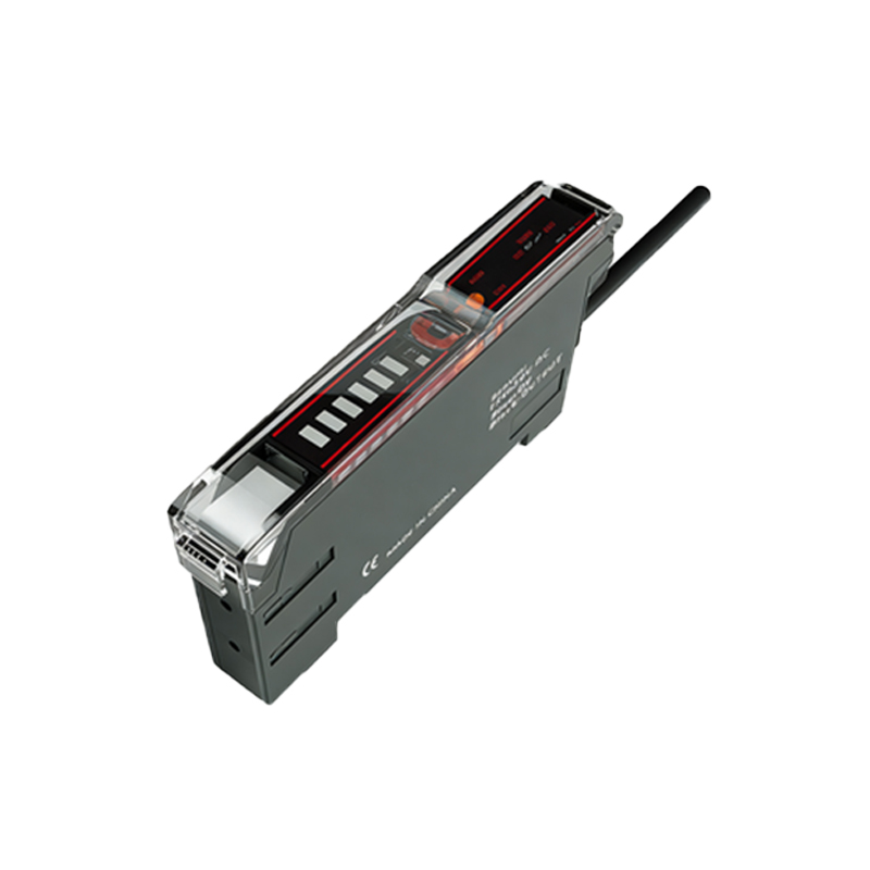
Common Symptoms of a Failing Sensor
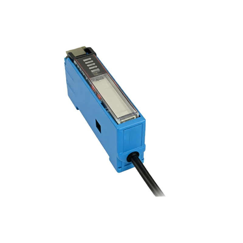
Recognizing the signs of a deteriorating sensor is crucial for preventative maintenance. The most obvious symptom is inconsistent or unreliable detection. The sensor may fail to detect a present object (a false negative) or may indicate detection when no object is within range (a false positive). Intermittent operation, where the sensor works sporadically, is another strong indicator of an impending failure. Physical inspection can also reveal problems. Look for cracks in the housing, cloudiness or damage to the lens, which can scatter or block light. Discoloration of the LED emitter, often visible through the lens, suggests overheating or age-related degradation. Additionally, if the sensor's indicator LED behaves erratically or does not illuminate during detection events, it points to an internal electronic fault.
Initial Visual and Environmental Checks
Before employing diagnostic tools, perform a thorough visual and environmental inspection. Ensure the sensor is securely mounted and properly aligned. Even slight misalignment, especially for retro-reflective sensors requiring precise alignment with a reflector, can cause complete failure. Examine the lens for any accumulation of dust, oil, dirt, or condensation, and clean it carefully with a soft, lint-free cloth and appropriate cleaner. Assess the operating environment. Excessive ambient light, such as direct sunlight or strobe lighting, can swamp the sensor's receiver. Verify that the electrical connections are tight and that the wiring is not damaged, frayed, or compromised. Check that the power supply voltage is within the sensor's specified range, as both over-voltage and under-voltage can cause abnormal behavior or permanent damage.
Testing with a Digital Multimeter
A digital multimeter (DMM) is an invaluable tool for basic electrical diagnostics. First, with power disconnected, check the sensor's output circuit for continuity or short circuits as per its datasheet (NPN sinking vs. PNP sourcing). With power applied, measure the voltage at the output terminal relative to the common wire. For a discrete DC sensor, the output should swing close to the supply voltage (e.g., 24V) in one state and near 0V in the other when an object is introduced and removed. A voltage that sits at an intermediate level or does not change may indicate a faulty output transistor. You can also use the DMM in diode test mode to check the health of the internal LED emitter (it should show a forward voltage drop, typically 1.2V-1.8V for infrared LEDs) and the phototransistor, though this often requires accessing internal circuitry.
Using an Oscilloscope for Advanced Diagnosis
For persistent or complex issues, an oscilloscope provides a dynamic view of the sensor's signals. Probe the output terminal to observe the switching waveform. A healthy sensor will show clean, fast transitions between high and low states. Excessive noise on the output line, slow rise/fall times, or ringing can indicate problems with the output driver or electrical interference. More advanced diagnosis involves probing the signal from the receiving phototransistor before it is processed by the comparator circuit. By observing the analog level of this received signal while moving a target in and out of range, you can assess the signal-to-noise ratio and the sensor's margin of operation. A weak or noisy received signal suggests a failing emitter, dirty lens, or degraded receiver.
Evaluating Sensing Range and Response Time
Performance degradation often manifests as a reduced effective sensing range. To test this, use a standard target with specified reflectivity (often a Kodak 90% white card) as stated in the sensor's datasheet. Gradually move the target toward the sensor from a distance beyond its rated range, noting the exact point where the output switches. Compare this to the manufacturer's specification. A significant reduction in range points to a weakening LED, dirty optics, or component aging. Similarly, test the sensor's response time by rapidly passing a target through its beam. Use an oscilloscope to measure the delay between the target edge crossing the beam center and the output state change. A response time that exceeds the datasheet value can cause missed detections in high-speed applications and indicates slowing internal electronics.
Cross-Comparison and Replacement Verification
One of the most practical field tests is cross-comparison with a known-good sensor of the same model. Install the suspected bad sensor and the known-good sensor side-by-side in the same application, ensuring identical mounting, alignment, and targets. Monitor their outputs simultaneously. Consistent discrepancies confirm a fault in the suspected unit. If a known-good sensor is not available, the definitive test is replacement. Install a new sensor with identical electrical and mechanical specifications. If the system returns to reliable operation, the original sensor was indeed faulty. Always ensure the replacement is correctly configured (e.g., light-on/dark-on mode, output type) to match the application requirements before concluding the diagnosis.