Understanding the Core Principle
Proximity sensors are non-contact electronic devices designed to detect the presence or absence of a target object within a defined sensing range without physical contact. The fundamental principle behind most industrial proximity sensors is electromagnetic induction or capacitive coupling. Inductive proximity sensors, the most common type, generate an oscillating electromagnetic field from a coil within the sensor head. When a metallic target enters this field, eddy currents are induced on the target's surface. These eddy currents draw energy from the sensor's oscillator circuit, causing a measurable change in its amplitude. This amplitude reduction is detected by a threshold circuit, which subsequently triggers a solid-state output switch, typically an NPN or PNP transistor. The schematic representation of this process encapsulates the entire signal path from oscillator generation to final output switching, providing a blueprint for understanding sensor behavior, troubleshooting, and integration into larger control systems.
Key Components in a Typical Schematic
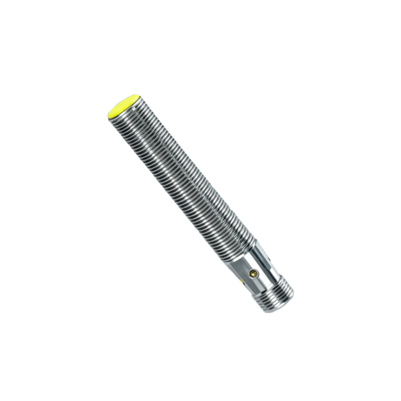
A standard inductive proximity sensor schematic can be deconstructed into several key functional blocks. The heart of the circuit is the LC Oscillator, consisting of the sensing coil (L) and a resonant capacitor (C). This oscillator generates the high-frequency electromagnetic field. Following this is the Demodulator or Amplitude Detection Circuit, which rectifies and filters the oscillator signal to produce a DC voltage level proportional to the oscillation amplitude. This DC level feeds into a Comparator or Threshold Circuit. Here, it is compared against a preset reference voltage. When the signal drops below the reference (indicating target presence), the comparator's output state changes. Finally, the Output Stage reacts to this change. This stage usually features a power transistor (for switching the load) and protective components like flyback diodes for DC sensors or surge suppressors for AC models, all crucial for reliable interfacing with Programmable Logic Controllers (PLCs) or relays.
Analyzing the Signal Path
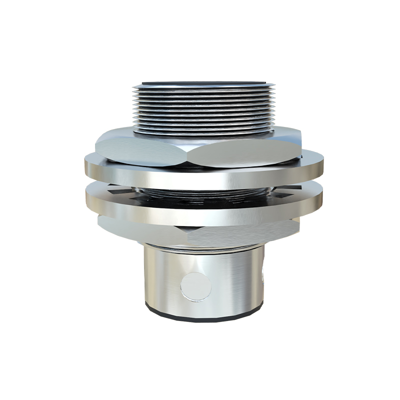
Tracing the signal path on the schematic is critical for diagnostics. Starting at the coil, the schematic shows its connection to the oscillator IC or transistor network. A drop in oscillation amplitude manifests as a voltage change at the demodulator's output node. On the schematic, test points are often indicated here. The comparator stage clearly shows the two inputs: the signal from the demodulator and the reference voltage, which may be adjustable in some designs via a potentiometer or fixed resistors. The output of the comparator directly drives the base or gate of the output switching transistor. By understanding this path, an engineer can use an oscilloscope to probe at each stage—observing the clean oscillation with no target, its attenuation with a target present, and the subsequent digital swing at the comparator output—to isolate faults to a specific functional block.
Output Configuration Variations
Schematics distinctly illustrate the different output configurations, which are paramount for correct wiring. The two primary types are NPN (Sinking) and PNP (Sourcing) outputs. In an NPN schematic, the output transistor is an NPN type, with the emitter connected to the common negative (0V) rail. The load is connected between the positive supply and the collector (output wire). When activated, the transistor sinks current from the load to ground. Conversely, a PNP schematic shows a PNP transistor with its emitter connected to the positive supply. The load is connected between the output (collector) and ground. Here, the transistor sources current from the positive supply to the load. The schematic also always includes protection components, such as a freewheeling diode across the load for DC models, which is essential for preventing voltage spikes from damaging the output transistor.
Power Supply and Protection Circuits
A robust proximity sensor schematic dedicates significant portion to power conditioning and protection. This includes voltage regulation to ensure stable operation for the oscillator and logic circuits despite fluctuations in the supply line (e.g., 10-30V DC). Reverse polarity protection, often achieved with a series diode or a bridge rectifier, prevents damage if power wires are accidentally reversed. For AC-powered sensors, a rectifier bridge is fundamental. Furthermore, schematics detail surge suppression devices like Metal-Oxide Varistors (MOVs) and filtering networks (capacitors and inductors) to protect against electromagnetic interference (EMI) and voltage transients from the mains or inductive loads. These elements are not merely ancillary; they are critical for ensuring the sensor's longevity and noise immunity in harsh industrial environments, and their failure is a common source of erratic operation.
Schematic as a Diagnostic Tool
For the field engineer, the schematic is an indispensable diagnostic tool. Common failure modes have clear signatures. A completely dead sensor may point to a failed