Introduction to Hysteresis in Sensing Technology
Inductive proximity sensors are widely used in industrial automation for non-contact detection of metallic objects. A critical parameter influencing their performance is hysteresis, which refers to the difference between the switch-on point (when the target approaches) and the switch-off point (when the target moves away). This phenomenon is intentionally designed into sensors to prevent output oscillation or chattering when a target is near the detection threshold. Without hysteresis, even minor vibrations or environmental fluctuations could cause erratic switching, leading to system instability. In essence, hysteresis provides a stable dead band, ensuring reliable operation in dynamic industrial environments.
The Physical Mechanism Behind Hysteresis
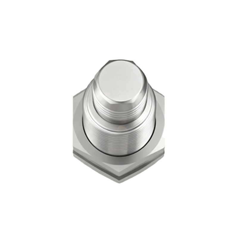
Hysteresis in inductive proximity sensors arises from the inherent properties of the oscillator and Schmitt trigger circuitry within the sensor. As a metallic target enters the sensing field, it induces eddy currents, dampening the oscillator's amplitude. The sensor triggers an output state change (e.g., from OFF to ON) at a specific amplitude threshold. However, due to the Schmitt trigger's design, the threshold for turning OFF the sensor is set lower than the turn-on threshold. This difference creates a hysteresis band, typically expressed as a percentage of the nominal sensing distance. For instance, a sensor with a 10 mm range might have a hysteresis of 3–10%, meaning the switch-off occurs 0.3–1 mm farther from the sensor than the switch-on point.
Calculating and Specifying Hysteresis Values
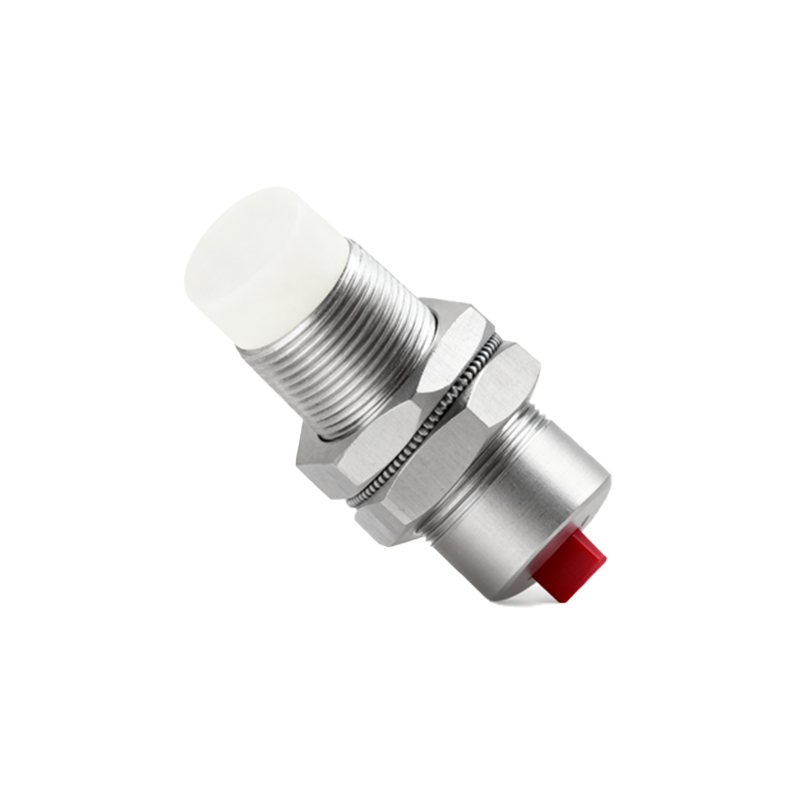
Manufacturers specify hysteresis in technical datasheets, often as a percentage of the rated operating distance (Sn). The exact value depends on sensor design, target material, and environmental conditions. To calculate hysteresis, engineers measure the approach distance (switch-on) and retreat distance (switch-off) under standardized conditions. For example, if a sensor switches on at 8 mm and off at 7 mm from a steel target, the hysteresis is 1 mm. As a percentage of an 8 mm sensing range, this equates to 12.5%. Industry standards like IEC 60947-5-2 define testing methods to ensure consistency. Understanding these specifications is crucial for selecting sensors suited to specific applications, such as high-precision positioning or general-purpose detection.
Impact of Hysteresis on System Performance
Hysteresis directly affects the accuracy, repeatability, and response time of inductive proximity sensors. In applications requiring precise positioning, minimal hysteresis is desirable to reduce dead zones. Conversely, in environments with vibration or target wobble, higher hysteresis enhances noise immunity. For instance, in conveyor systems detecting metal parts, adequate hysteresis prevents false triggers caused by part jitter. However, excessive hysteresis can delay detection during rapid cycling, potentially reducing throughput. Engineers must balance hysteresis with other factors like switching frequency and temperature stability to optimize overall system reliability.
Optimizing Hysteresis for Different Applications
Selecting the right hysteresis level involves analyzing operational conditions. In automotive assembly lines, sensors with moderate hysteresis (5–8%) are common to tolerate mechanical tolerances. For precision robotics, low-hysteresis sensors (<3%) provide finer control. Advanced sensors offer adjustable hysteresis via potentiometers or digital interfaces, allowing customization in-field. Additionally, target material influences hysteresis; ferrous metals typically yield higher hysteresis than non-ferrous ones due to stronger magnetic interactions. Regular calibration and environmental monitoring (e.g., temperature compensation) help maintain hysteresis consistency over time, ensuring long-term performance.
Future Trends and Innovations
Emerging technologies are reshaping hysteresis management in inductive sensors. Smart sensors with integrated microprocessors can dynamically adjust hysteresis based on real-time feedback, adapting to changing conditions like target speed or contamination. Wireless sensor networks leverage data analytics to predict hysteresis drift, enabling predictive maintenance. Furthermore, miniaturized designs with improved core materials reduce inherent hysteresis, expanding applications in electronics and medical devices. As Industry 4.0 advances, the integration of hysteresis parameters into digital twins will enhance simulation accuracy, allowing for virtual optimization before physical deployment.
Conclusion and Best Practices
Hysteresis is a fundamental characteristic of inductive proximity sensors, bridging theoretical design and practical usability. Engineers should prioritize evaluating hysteresis during sensor selection, referencing datasheets and conducting real-world tests. Key practices include matching hysteresis to application stability needs, considering target material effects, and implementing regular maintenance schedules. By mastering hysteresis principles, professionals can enhance system robustness, minimize downtime, and drive innovation in automation. Ultimately, a nuanced understanding of this parameter empowers more efficient and reliable industrial solutions.