Introduction to Photoelectric Sensor Signal Levels
In the realm of industrial automation, photoelectric sensors serve as the critical eyes of a system, detecting the presence, absence, or position of objects without physical contact. The core functionality of these sensors is translated into an electrical signal that control systems like PLCs (Programmable Logic Controllers) can interpret. This interpretation hinges on two fundamental states: the high level and the low level. These binary states form the basic language of communication between the sensor and the controller. A high-level signal, often referred to as a logic '1', typically represents a voltage close to the sensor's supply voltage, indicating a specific condition, such as an object being detected. Conversely, a low-level signal, or logic '0', represents a voltage near zero volts, indicating the opposite condition, like the absence of an object. Understanding the generation, characteristics, and application of these signal levels is paramount for designing robust and reliable automated processes.
Defining High and Low Level Voltage Thresholds
The specific voltage values that constitute a high or low level are not universal; they are defined by the sensor's output circuit technology and the supply voltage. For sensors operating on a 24 VDC supply, which is standard in industrial environments, a high-level output (often from a PNP or sourcing output) might be in the range of 22-24 VDC when active. A low-level output (from an NPN or sinking output) would be close to 0 VDC. For sensors interfacing with 5V logic circuits, such as some microcontroller-based systems, a high level is typically >2.0V to 5V, and a low level is<0.8V. The region between these defined thresholds is an indeterminate state that control systems must be designed to avoid, as it can lead to erratic behavior. Modern photoelectric sensors clearly specify these thresholds in their datasheets under parameters like "On-state voltage" and "Off-state voltage" or "Residual voltage."
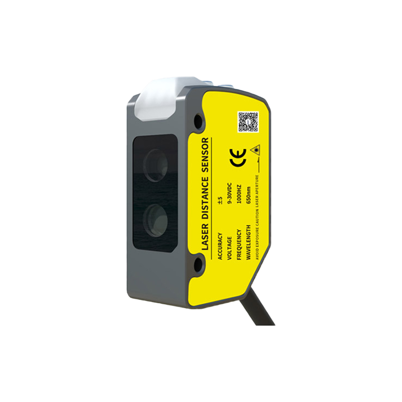
Output Circuit Configurations: PNP vs. NPN
The generation of high or low signals is intrinsically linked to the sensor's transistor-based output circuit. The two primary types are PNP (sourcing) and NPN (sinking) outputs. A PNP sensor switches the positive side of the load. When active (object detected), it connects the load to the positive supply voltage, providing a high-level signal to the input of a PLC or other device. An NPN sensor switches the negative or ground side of the load. When active, it connects the load to ground (0V), providing a low-level signal relative to the supply. The choice between PNP and NPN is crucial and depends on the input circuit of the receiving controller. Many regions have a standard preference; for instance, PNP (sourcing) is commonly used with PLCs that have sinking inputs in Europe and many parts of the world, while NPN is historically associated with certain Japanese and North American designs.
Light-On vs. Dark-On Operation Modes
The logical relationship between the detected light condition and the output signal level is defined by the sensor's operating mode: Light-On or Dark-On. This is a fundamental programming or configuration setting. In Light-On mode (also called "light operate"), the sensor's output switches to the active state (e.g., high level for a PNP) when the receiver detects sufficient light from the emitter. This is typical for through-beam or retro-reflective sensors when no object is blocking the beam. In Dark-On mode ("dark operate"), the output becomes active when the light path is blocked (dark condition). This mode directly affects whether an object's presence is signaled by a high or low level. For example, a PNP sensor in Dark-On mode will output a high level when an object is present (blocking light). Understanding and correctly configuring this mode is essential for the intended logic of the control program.
Interfacing with Control Systems and PLCs
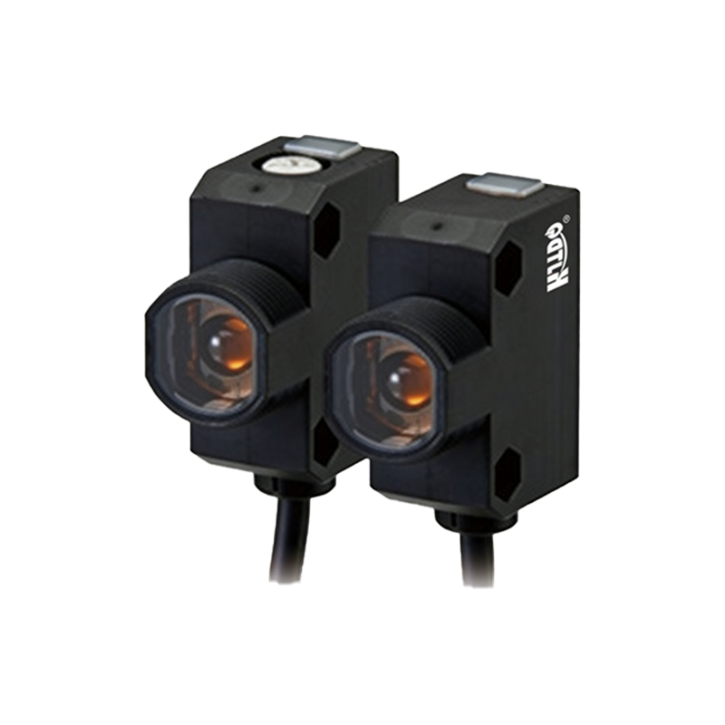
Successful integration of a photoelectric sensor into an automation system requires correct electrical interfacing. The sensor's output level must be compatible with the input module of the PLC or controller. Mismatches can lead to non-operation or damage. For a PLC with a sinking input (which internally connects to the positive supply), a PNP (sourcing) sensor is required. The active high signal from the PNP completes the circuit to the PLC's input. For a PLC with a sourcing input (internally connected to ground), an NPN (sinking) sensor is needed. The active low signal from the NPN completes the circuit. Additionally, factors like load current, switching speed, and the need for pull-up or pull-down resistors (for open-collector outputs) must be considered to ensure a clean, stable signal free from electrical noise, which is abundant in industrial settings.
Troubleshooting Signal Level Issues
Common issues in photoelectric sensing often revolve around incorrect or unstable signal levels. Troubleshooting begins with verifying the output state. Using a multimeter, measure the voltage between the sensor's output wire and the common (0V) wire. Compare the measured voltage in the "object present" and "object absent" states against the datasheet specifications. An output stuck high or low could indicate a failed output transistor, incorrect mode (Light-On/Dark-On), misalignment, insufficient light, or a dirty lens. Electrical noise can cause a signal to flicker between levels, leading to erratic machine behavior. This can be mitigated by using shielded cables, proper grounding, and ensuring the sensor's load (like a PLC input) is within its rated capacity. Understanding the expected high/low behavior is the first step in systematic fault diagnosis.
Advanced Considerations and Selection Criteria
Beyond basic operation, several advanced features influence signal behavior. Some sensors offer programmable outputs, allowing the user to invert the output logic or set a one-shot pulse. Analog output sensors provide a variable voltage or current proportional to the received light intensity, offering more information than a simple high/low. For high-speed applications, the response time—the delay between the sensing event and the output switching—is critical. Furthermore, the choice of output type (relay, solid-state) and protection features (short-circuit, reverse polarity, surge protection) impact reliability. When selecting a sensor, engineers must define the required signal level type (PNP/NPN), the operating mode, switching frequency, environmental robustness (IP rating), and ensure compatibility with the control system's input characteristics to guarantee seamless and dependable operation in the intended application.