Introduction to Slot Type Photoelectric Sensors
Slot type photoelectric sensors, often called through-beam sensors, consist of two separate units: an emitter and a receiver. These units are housed in a single U-shaped body with a slot in between. The emitter continuously transmits a light beam, typically infrared or visible red, across the gap to the receiver. When an object passes through the slot, it interrupts this beam, causing the sensor's output state to change. This simple, non-contact detection method makes them ideal for counting, positioning, and detecting the presence or absence of objects in automation and machinery. Understanding their basic working principle is the first step before proceeding to any wiring task.
Essential Tools and Safety Precautions
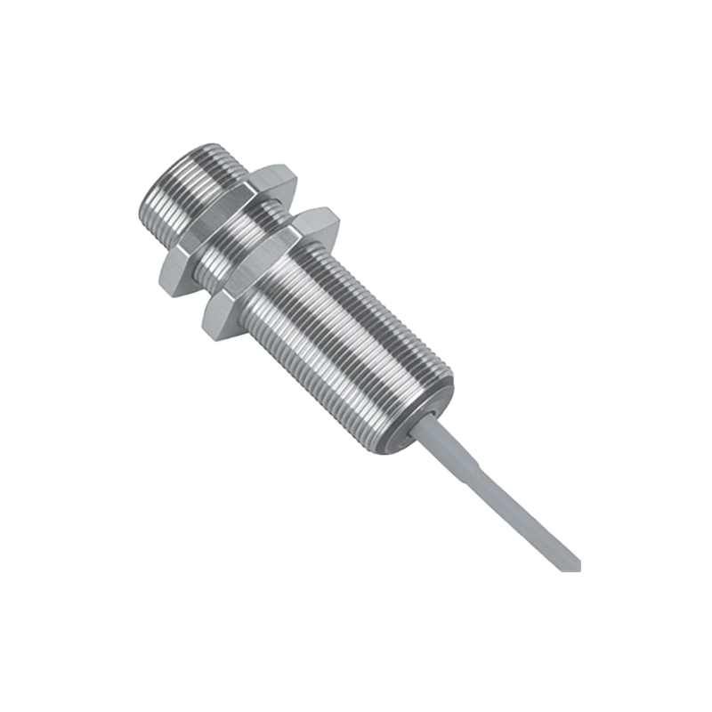
Before starting the wiring process, gather all necessary tools and components. You will typically need a slot sensor, a DC power supply (commonly 12-24V DC), connecting wires, a screwdriver, and possibly a multimeter for verification. Always prioritize safety. Ensure the power is completely disconnected before making any electrical connections. Verify the voltage rating of your specific sensor model against your power supply to prevent damage. Wear appropriate personal protective equipment if working in an industrial environment. Double-check the manufacturer's datasheet for your sensor's exact specifications, as pin configurations and voltage tolerances can vary between models and brands.
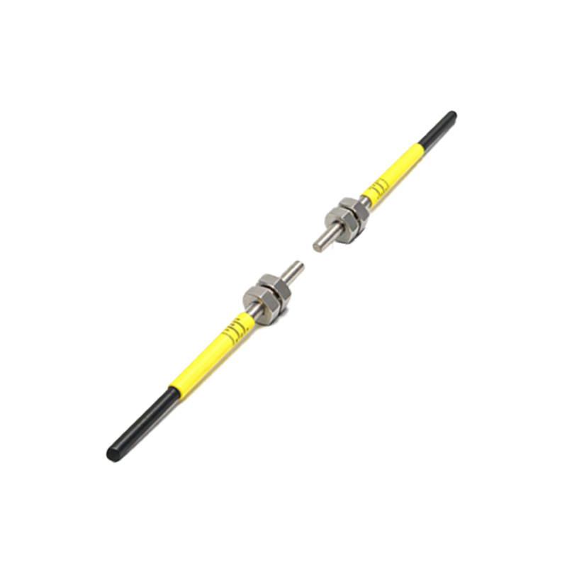
Understanding the Wiring Diagram and Pinout
The cornerstone of correct installation is interpreting the wiring diagram. Most standard three-wire DC slot sensors have the following terminal designations: Brown wire (or +V): This is the positive power supply input. Blue wire (or 0V): This is the negative power supply/common ground. Black wire (or OUT): This is the switched output signal wire. Some sensors may have a white wire for a complementary output or other functions. The housing or datasheet will clearly label these. It is critical to identify these pins correctly. A typical NPN output sensor will sink current to ground, while a PNP type will source current from the positive supply. Confirming whether you have an NPN or PNP sensor is vital for compatibility with your controller (PLC, relay, etc.).
Step-by-Step Wiring Procedure
Begin by securely mounting the sensor in its desired location. First, connect the power wires. Attach the brown wire from the sensor to the positive terminal (+) of your DC power supply. Connect the blue wire from the sensor to the negative terminal (-) of the power supply. Next, connect the output wire. For an NPN sensor, the black output wire should be connected to the input terminal of your load (e.g., a PLC input module), and the other side of that load must then be connected to the positive supply. For a PNP sensor, the black wire connects to the load, and the other side of the load connects to the negative supply. Ensure all connections are tight and secure to avoid intermittent faults.
Testing and Troubleshooting the Connection
After wiring, do not immediately assume the setup is complete. Apply power to the system. Most sensors have a built-in LED indicator. When powered and no object is in the slot, the LED is usually steady or off (depending on the model's logic). When an object interrupts the beam, the LED state should change, and the output should activate. Use a multimeter to measure the voltage between the black output wire and the blue wire (for NPN) or brown wire (for PNP) to confirm the switching action. If the sensor does not respond, re-check all connections against the diagram. Verify the power supply voltage. Ensure the object is suitable for detection (opaque enough to break the beam) and is passing completely through the slot.
Practical Application and Video Tutorial Insights
A video tutorial visually demonstrates the nuances that a manual might miss. It shows the physical handling of the wires, the sound of a click when a screw terminal is properly tightened, and the real-time response of the indicator LED. In a video, you can see practical applications, such as connecting the sensor to a programmable logic controller (PLC) or a simple relay to control a machine process. The video might also cover advanced topics like wiring in a series for safety interlocks or parallel connections for multiple detection points. Watching the sensor perform in real-time with a test object solidifies the theoretical knowledge gained from datasheets and articles.
Common Mistakes and Best Practices
Several common errors can lead to sensor failure or unreliable operation. These include reversing the power polarity (connecting brown to negative), which can permanently damage the sensor. Another mistake is over-tightening terminal screws, which can strip the threads or cut the wire strands. Using an incorrect voltage supply is also a frequent issue. For best practices, always use ferrules or tinned wire ends for a clean connection in screw terminals. Route sensor cables away from high-power motor cables to avoid electrical noise interference. Implement proper strain relief so that the wires are not bearing the weight of the cable. Finally, keep the sensor's lens clean from dust and debris, which can attenuate the light beam and reduce sensing range.