Understanding the Role of Parallel Resistors in Sensor Circuits
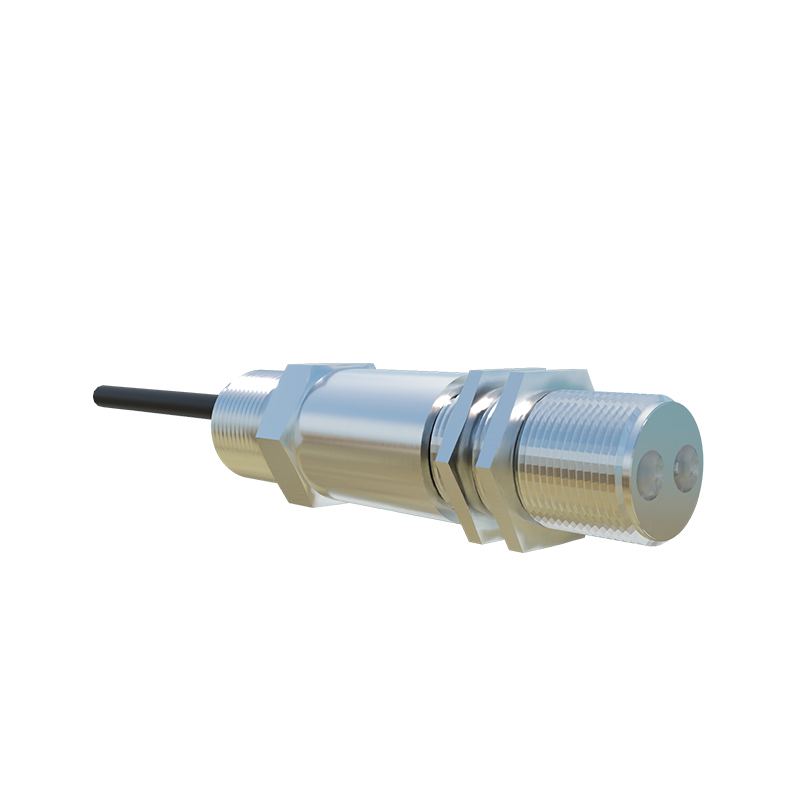
In the realm of industrial automation and control systems, photoelectric sensors are indispensable for detecting the presence, absence, or position of objects. A critical, yet often overlooked, component in optimizing the performance of these sensors, particularly in their output stages, is the parallel resistor. This passive component is strategically placed across the output terminals of a sensor, fundamentally altering its electrical behavior to ensure compatibility with the connected load, typically a Programmable Logic Controller (PLC) input module or a relay. The primary function is to provide a defined current path, which becomes crucial when dealing with different sensor output types like NPN (sinking) or PNP (sourcing) transistor configurations. Without proper understanding and application, mismatched loads can lead to unreliable operation, false triggering, or even damage to the sensor or the controller.
The Electrical Principle: Leakage Current and False Signals
The core challenge addressed by a parallel resistor is the phenomenon of leakage current. Modern solid-state sensors, even in their "OFF" state, allow a small amount of current, known as leakage current, to flow through their output transistor. When connected to a high-impedance PLC input, this tiny current can build up enough voltage to be misinterpreted by the PLC as an "ON" or logic "1" signal, causing a false trigger. This is particularly problematic with 3-wire DC sensors. By connecting a resistor in parallel with the sensor's output and the PLC input, we create an alternative, preferential path for this leakage current. The resistor's value is chosen to be significantly lower than the input impedance of the PLC. Consequently, the voltage developed across the parallel combination due to leakage current is kept below the PLC's guaranteed "OFF" state voltage threshold, ensuring a clean and reliable "OFF" signal.
Calculating the Optimal Resistor Value
Selecting the correct resistor value is a precise calculation that balances several factors. The key parameters are the sensor's maximum leakage current (I_leakage, typically found in the datasheet, e.g., 1.5mA) and the PLC input's maximum "OFF" state voltage (V_off, often 5V for a 24V system). Ohm's Law provides the foundation: R_parallel ≤ V_off / I_leakage. For instance, with V_off = 5V and I_leakage = 1.5mA, the maximum resistor value would be approximately 3.33 kΩ. A standard value like 3.3 kΩ or a lower value such as 2.2 kΩ is often chosen for a safety margin. However, one must also consider the power rating. The resistor must dissipate power when the sensor is active. The power dissipation (P) is calculated using P = V_supply² / R. For a 24V system and a 2.2kΩ resistor, P ≈ 0.26W, so a standard 0.5W or 0.6W resistor is sufficient. Using a value that is too low will unnecessarily load the sensor's output transistor when ON, potentially causing overheating.
Application Scenarios: NPN vs. PNP Outputs
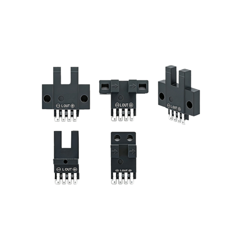
The need for and placement of a parallel resistor depends heavily on the sensor's output type. For a standard NPN (sinking) output sensor, the output transistor connects the signal line to common (0V) when active. Here, the parallel resistor is typically connected between the sensor's output wire (usually black) and the positive supply voltage (+V). This "pull-up" resistor ensures the signal line is at a defined high voltage when the NPN transistor is OFF, preventing it from floating and picking up noise. For a PNP (sourcing) output sensor, the output transistor connects the signal line to +V when active. In this case, a "pull-down" resistor is connected between the output wire and common (0V). This ensures a defined low voltage when the PNP transistor is OFF. While the leakage current mitigation is a primary driver for pull-down resistors on PNP outputs, pull-up resistors on NPN outputs also serve to define the logic state clearly.
Practical Installation and Troubleshooting Tips
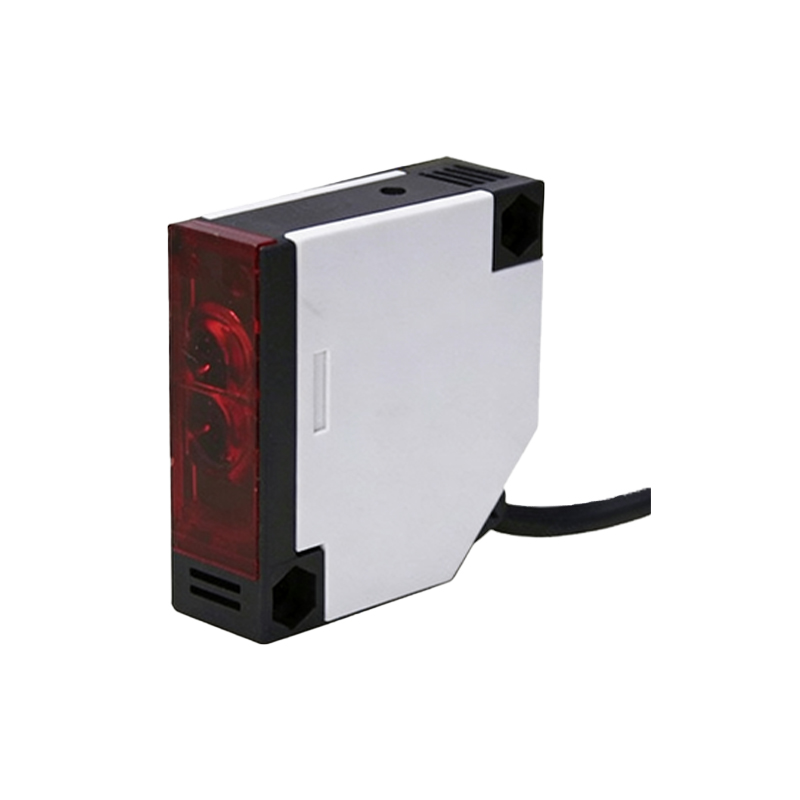
In field installations, the parallel resistor is often housed inside the sensor's connector hood or in a small junction box near the PLC terminal block. It is vital to ensure secure connections to prevent intermittent faults. When troubleshooting a system suspected of false triggering, measuring the voltage at the PLC input with the sensor commanded OFF is the first step. If the voltage is measured to be close to or above the PLC's OFF threshold, adding or adjusting a parallel resistor is the standard remedy. Conversely, if a sensor seems to be underperforming or getting hot, verify that the parallel resistor value is not excessively low, causing an overcurrent condition in the output stage. Always consult both the sensor and the PLC input module datasheets for specific leakage current figures and voltage thresholds, as they can vary significantly between manufacturers and models.
Advanced Considerations and Alternatives
Beyond basic leakage current management, parallel resistors can be used in more advanced configurations. In some cases, a resistor-capacitor (RC) snubber network in parallel is used to suppress voltage spikes from inductive loads, such as relay coils connected to the sensor output. For systems with extremely high noise immunity requirements, specialized input modules with built-in "bleeder" circuits or a lower input impedance are available, potentially eliminating the need for an external resistor. Furthermore, in analog output photoelectric sensors or those with configurable outputs, the role of external resistors shifts towards scaling or signal conditioning. The fundamental principle, however, remains: the parallel resistor is a simple, cost-effective component that ensures the integrity of the digital signal in a noisy industrial environment, bridging the gap between sensor operation and controller expectation.