Understanding the Core Components
An AC photoelectric sensor and a relay are fundamental components in countless industrial automation systems. The photoelectric sensor acts as the "eyes" of the operation, detecting the presence, absence, or distance of an object using a light beam. The AC variant operates on alternating current, commonly 120VAC or 240VAC, aligning with standard industrial power supplies. The relay, on the other hand, functions as a robust electrically operated switch. It uses a low-power signal from the sensor to control a separate, higher-power circuit, such as turning on a motor, activating a solenoid valve, or sounding an alarm. The primary goal of connecting these two devices is to translate a simple detection event into a significant mechanical action, enabling automated control and safety interlocking.
Critical Pre-Wiring Considerations
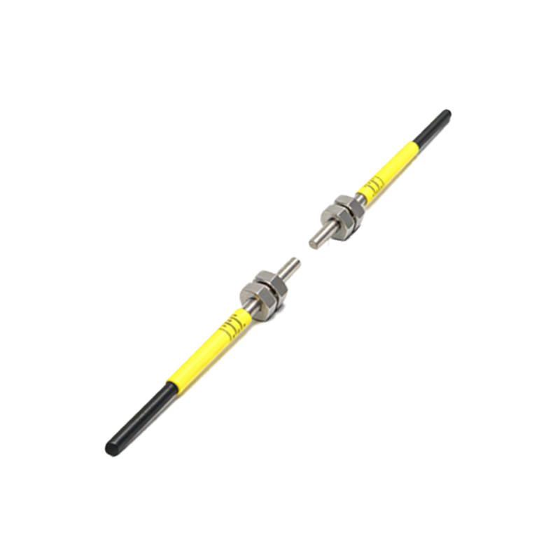
Before any connection is made, a thorough review of the manufacturer's datasheets for both the sensor and the relay is non-negotiable. First, verify the voltage ratings. The sensor's output type must be compatible with the relay's coil. For an AC sensor, the output is typically a solid-state switch (like a Triac) designed for AC loads. Ensure the sensor's load current rating exceeds the inrush and holding current requirements of the relay coil. Second, identify the wiring configuration. Most industrial AC photoelectric sensors have three core wires: Brown (Line/Live), Blue (Neutral), and Black (Output/Load). The relay coil will have two terminals for power (e.g., A1 and A2). The key is to connect the sensor's output in series with the relay's coil. Additionally, always adhere to local electrical codes, implement proper lockout-tagout procedures, and ensure all power is disconnected during installation.
Standard Wiring Connection Procedure
A typical wiring scheme for a 3-wire AC sensor is as follows. Connect the Brown wire from the sensor directly to the AC Line (Hot) source. Connect the Blue wire from the sensor directly to the AC Neutral source. This provides operating power to the sensor's internal circuitry. The critical connection is the Black (output) wire. This wire should be connected to one terminal of the relay coil (e.g., terminal A1). Finally, connect the other relay coil terminal (e.g., A2) back to the AC Neutral source. This creates a complete circuit: AC Hot -> Sensor (Internal Circuit) -> Sensor Output (Black) -> Relay Coil (A1 to A2) -> AC Neutral. When the sensor detects an object, its internal solid-state switch closes, allowing current to flow through the relay coil, energizing it and closing its contacts.
Integrating Protective Components
To ensure longevity and reliability, incorporating protective devices is highly recommended. A fuse or circuit breaker on the AC Line side, rated appropriately for the combined load, is essential for overcurrent protection. For the relay coil, a Metal Oxide Varistor (MOV) or a RC snubber circuit connected across the coil terminals (A1 and A2) is crucial. This suppresses voltage spikes and electrical noise generated by the inductive kick of the relay coil when it de-energizes. These transient voltages can damage the sensor's sensitive solid-state output over time. Furthermore, in electrically noisy environments, using shielded cable for the sensor's output connection to the relay and grounding the shield properly can prevent false triggering.
Testing and Troubleshooting Steps
After wiring, a methodical test sequence is vital. Restore power and observe the sensor's indicator LED. It should illuminate steadily when not detecting a target and change state (e.g., blink or turn off) when an object is present. Next, trigger the sensor. You should hear and feel a distinct click from the relay as it energizes. Use a multimeter to verify voltage across the relay coil when activated. If the relay does not energize, check for loose connections, verify the sensor's light beam is correctly aligned and not obstructed, and confirm the power supply voltage. If the relay chatters or behaves erratically, it often indicates insufficient current from the sensor or a mismatch in load type—ensure the sensor's minimum load current requirement is met by the relay coil.
Advanced Applications and Best Practices
This basic connection forms the building block for more complex functions. For instance, by wiring the sensor to a relay with multiple contacts (e.g., NO and NC), you can control two opposing actions. A timer relay can be inserted between the sensor and the control relay to add delay-on or delay-off functions. For safety-critical applications, such as light curtains or area guards, a safety relay must be used instead of a standard relay to meet required performance levels. A universal best practice is to always draw a clear ladder diagram or schematic before wiring. Use high-quality industrial-grade components, secure all wires in duct or with cable ties, and label every wire and terminal clearly for future maintenance.