Understanding 2-Wire Proximity Sensor Fundamentals
A 2-wire proximity sensor is a simple yet robust device widely used in industrial automation for detecting the presence or absence of metallic objects without physical contact. Unlike their 3-wire or 4-wire counterparts, these sensors integrate the switching element directly into the power supply line. This design simplifies installation but introduces specific considerations for proper operation. The core principle involves the sensor drawing a small leakage current, or "off-state current," when in its idle state. When a target enters its sensing range, the internal switch closes, allowing the full load current to flow. This two-wire configuration means there is no separate wire for the output signal; the same two wires carry both the power supply and the switched load current. This makes them ideal for replacing mechanical limit switches in AC or DC circuits, offering a solid-state, wear-free alternative.
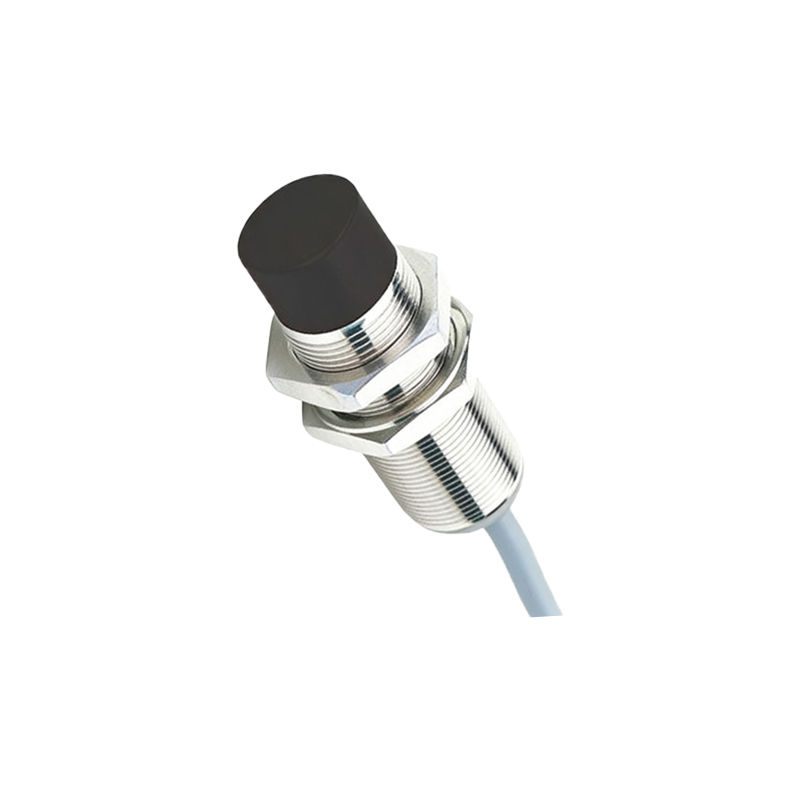
Essential Components and Wiring Diagram
Before beginning any wiring procedure, gather the necessary components: the 2-wire proximity sensor itself, a compatible power supply (AC or DC as specified by the sensor's datasheet), the load (such as a relay coil, PLC input, or contactor), and appropriate cabling. The fundamental wiring diagram is straightforward. One wire from the sensor connects to one terminal of the power supply (L+ for DC positive or L for AC line). The other wire from the sensor connects directly to one terminal of the load. The remaining terminal of the load then connects back to the other terminal of the power supply (L- for DC negative or N for AC neutral). This forms a complete series circuit: Power Supply -> Sensor -> Load -> Power Supply. It is critical to verify the sensor's voltage rating (e.g., 10-30V DC, 20-250V AC) and ensure the power supply matches this range precisely.
Step-by-Step Wiring Procedure for DC Circuits
For DC (Direct Current) applications, polarity is a key factor. First, de-energize the entire circuit. Identify the sensor's wiring markings, typically labeled as +V (or 1) and -V (or 2). Connect the wire from the +V terminal to the positive pole (L+) of your DC power source. Connect the wire from the -V terminal to one side of your load device. Finally, connect the other side of the load device back to the negative pole (L-) of the DC power source. This configuration ensures the sensor is correctly polarized. Upon powering up, an LED indicator on the sensor (if present) may glow dimly, indicating the off-state leakage current. When a metal target is presented to the sensing face, the LED should brighten significantly, and the load should be energized. Always use a multimeter to confirm voltage levels at the load under both on and off conditions.
Step-by-Step Wiring Procedure for AC Circuits
Wiring for AC (Alternating Current) circuits follows a similar series pattern but without concern for polarity. After ensuring the circuit is de-energized, connect one wire from the sensor (often labeled L or 1) to the Line (L or Hot) conductor of the AC power supply. Connect the other sensor wire (often labeled T or 2) to one terminal of the AC load. Connect the remaining load terminal to the Neutral (N) conductor of the AC power supply. In AC systems, it is paramount to incorporate proper fusing and potentially a surge suppressor near the sensor to protect against voltage transients common in industrial environments. The behavior is analogous to the DC circuit: a small leakage current maintains the circuit in the "off" state until a target triggers the sensor, allowing full current to pass through the load.
Critical Considerations for Load Compatibility
The successful operation of a 2-wire sensor hinges on load compatibility. The primary challenge is the off-state leakage current, typically ranging from 1 to 3 mA. This current must be low enough not to inadvertently activate the connected load, a phenomenon known as "phantom triggering." For instance, a relay or PLC digital input may have a minimum operating current. The sensor's leakage current must be below this threshold. Conversely, the sensor has a minimum operating current requirement to power its internal electronics. The load current when the sensor is "on" must meet or exceed this minimum, often around 3-5 mA, while staying below the sensor's maximum switching current. Always consult both the sensor datasheet and the load device specifications to ensure these current parameters are compatible for reliable switching.
Troubleshooting Common Installation Issues
Several common issues can arise when wiring 2-wire proximity sensors