Understanding Photoelectric Sensor Alignment Fundamentals
Proper alignment is the cornerstone of reliable photoelectric sensor operation in industrial automation. These sensors function by emitting a beam of light—visible red, infrared, or laser—toward a receiver or a reflector. The core principle of alignment is to ensure this beam strikes the target detection point with precision and that the receiver accurately captures the reflected or transmitted light signal. Misalignment, even by a few millimeters or degrees, can lead to false triggers, missed detections, and costly production downtime. Before beginning the physical alignment process, it is critical to understand the sensor's operating mode: through-beam, retro-reflective, or diffuse. Each mode has distinct alignment requirements and tolerances. Through-beam sensors, with separate emitter and receiver units, demand the most precise coaxial alignment. Retro-reflective types, which bounce light off a dedicated reflector, are more forgiving but require careful angular positioning to avoid optical crosstalk. Diffuse sensors, detecting light reflected directly from the target, have the least stringent alignment needs but are sensitive to target color and surface properties. A foundational grasp of these modes informs the entire alignment strategy.
Pre-Alignment Preparation and Safety Protocols
A systematic approach begins with thorough preparation. First, consult the sensor's datasheet for its specific technical specifications, including beam characteristics, sensing distance, and recommended alignment tolerances. Gather necessary tools: a stable mounting fixture, appropriate wrenches or screwdrivers, and, for critical applications, a laser alignment tool or the sensor's built-in alignment aid, such as a visible beam or alignment indicator LEDs. Always adhere to lock-out/tag-out (LOTO) procedures to de-energize the machinery and ensure a zero-energy state before starting work. Verify that the sensor's mounting location is rigid, free from vibration, and provides an unobstructed optical path. Clean the lens of both the emitter and receiver (or reflector) using a soft, lint-free cloth to remove dust, oil, or debris that could attenuate the light beam. For through-beam setups, temporarily mount the units in their approximate positions, ensuring they are facing each other squarely.
Step-by-Step Alignment Procedure for Through-Beam Sensors
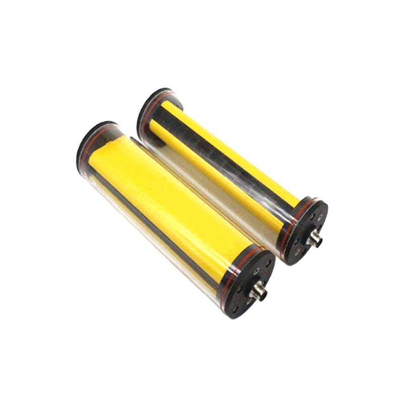
For through-beam sensors, achieving a coaxial beam path is paramount. Begin by roughly positioning the emitter and receiver units opposite each other. Many modern sensors feature a visible red beam or a "beam-on" indicator LED. Activate this function to provide a visual reference. Loosen the mounting hardware just enough to allow adjustment. Carefully adjust the emitter's horizontal and vertical position until its beam appears centered on the receiver's lens. Use the receiver's alignment indicator—often a set of LEDs that show signal strength—to fine-tune the position. The goal is to achieve the maximum or "green" signal level. For long-range alignments or in environments with limited visibility, a laser alignment tool is invaluable. It can be mounted in place of the sensor to project a precise dot onto the target point, guiding accurate mounting. Once optimal signal strength is indicated, gradually tighten the mounting hardware in a cross-pattern to avoid shifting the sensor, constantly monitoring the signal level during the process.
Alignment Techniques for Retro-Reflective and Diffuse Sensors
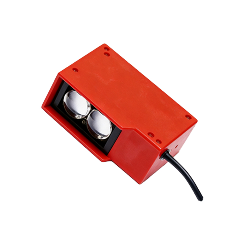
Aligning a retro-reflective sensor involves positioning it so its emitted beam strikes the center of the reflector perpendicularly and returns along the same path. Mount the sensor and reflector approximately facing each other. Use the sensor's alignment indicator to adjust its angle. A common challenge is avoiding detection of shiny surfaces other than the intended reflector, known as optical crosstalk. To mitigate this, slightly offset the sensor's axis so that its return beam is not perfectly coaxial, or use a polarized filter sensor with a corner-cube reflector. For diffuse (proximity) sensors, alignment focuses on ensuring the target object passes within the sensor's defined sensing window at the correct distance. The sensing window is often conical. Use the target object itself during setup. Move the target through its expected path while observing the sensor's output indicator. Adjust the sensor's position and angle until it reliably detects the target at the desired point and does not trigger on background objects. Pay close attention to the sensor's background suppression settings if applicable.
Verification, Testing, and Troubleshooting Common Issues
After alignment, rigorous verification under real operating conditions is essential. Do not rely solely on alignment indicators. Simulate the actual process by running the target material or machine part through the detection cycle multiple times at normal operating speed. Monitor the sensor's output using a programmable logic controller (PLC) diagnostic panel or a multimeter to check for consistency. Environmental factors like ambient light, dust, steam, or vibration can affect performance post-alignment. Install protective shrouds or hoods if strong ambient light is present. For persistent issues, methodical troubleshooting is required. If the signal is unstable, check for loose mounting, mechanical vibration, or a dirty lens. Intermittent failures might indicate marginal alignment; re-verify the beam path. False triggers could be caused by reflective surfaces in the background; adjust the sensor's angle or sensitivity threshold. Always document the final alignment settings and signal strength values for future maintenance reference.
Advanced Tips for Maintaining Long-Term Alignment Stability
Ensuring alignment persists over time requires proactive measures. Invest in high-quality, rigid mounting brackets designed for photoelectric sensors to resist shock and vibration. Consider sensors with robust housings (e.g., metal) for harsh environments. For critical applications, implement sensors with advanced features like automatic alignment monitoring and drift compensation. Regularly scheduled preventive maintenance should include a visual inspection of the optical path and a check of the signal strength without disturbing the alignment. Applying thread-locking compound to mounting screws after final alignment can prevent loosening. In settings with significant thermal fluctuation, be aware that thermal expansion of machinery can shift alignment; sensors with wider beam angles or background suppression may offer more resilience. Finally, training maintenance personnel on proper alignment procedures is as crucial as the initial setup, ensuring long-term system reliability and minimizing unplanned stoppages.