Understanding NPN Sensors and Proximity Switches
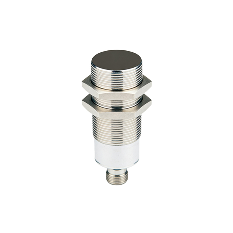
In industrial automation, sensors form the critical interface between the physical world and control systems. An NPN sensor is a type of solid-state switching device where the output transistor is an NPN type. This means that when the sensor is activated, it switches the output to connect the load to the common negative (0V) rail. Proximity switches, specifically inductive or capacitive types, are non-contact sensors that detect the presence or absence of metallic or other objects. When combined, an NPN proximity sensor is a common choice for many machine safety and sequencing applications due to its compatibility with standard programmable logic controller (PLC) sinking input modules. The fundamental principle is that the sensor's output acts as a switch to ground, completing a circuit when a target is detected.
The Principle of Interlocking for Safety and Control
Interlocking is a fundamental safety and control methodology in electrical engineering. It ensures that certain operations or machine movements cannot occur unless specific conditions are met, thereby preventing hazardous situations, equipment damage, or faulty sequences. For instance, a guard door must be confirmed closed via a proximity switch before a machine can start, or a robot arm should not move into an area if a sensor detects an operator's presence. An electrical interlock typically uses the status signal from one device (like a sensor) to control the power or logic enabling another device (like a motor starter or a PLC input). Using an NPN sensor for this purpose provides a reliable, low-voltage control signal that is isolated from the main power circuits.
Wiring Configuration for NPN Sinking Output
The correct wiring is paramount for a functional and safe interlock circuit. A typical three-wire NPN proximity switch has brown (positive), blue (common/negative), and black (output) wires. For interlocking with a PLC digital input, the standard wiring is as follows: Connect the brown wire to the positive DC supply voltage (e.g., +24VDC). Connect the blue wire to the 0V (common) of the same DC supply. The black output wire is connected to the input terminal of the PLC. Crucially, the PLC input module itself must be configured as a sourcing type or have an internal pull-up resistor to the positive supply. This creates a circuit where, when the sensor detects an object, the NPN transistor turns on, connecting the PLC input to 0V (sinking the current), which the PLC reads as an active 'ON' or 'TRUE' state. This signal is then used in the control logic to enable or disable other processes.
Implementing the Interlock Logic in the Control System
The physical wiring provides the signal; the logic within the control system enforces the interlock. In a PLC ladder logic program, the input from the NPN proximity sensor (e.g., I0.0) is used as a normally open (NO) or normally closed (NC) contact, depending on the safety philosophy. For a safety gate, you might use a normally closed logic configuration so that if the wire is cut or the sensor fails, the machine stops (a fail-safe design). This input contact is placed in series with the coil of the output controlling the machine. The rung might look like: [Start PB] AND [Sensor I0.0] AND [Other Conditions] = [Motor Starter Q0.0]. Only when all conditions, including the sensor being in the correct state, are met will the output energize. This software interlock, backed by the hardware signal, creates a robust control chain.
Practical Considerations and Best Practices
Several practical aspects ensure long-term reliability. First, always refer to the manufacturer's datasheets for voltage ratings, current sinking capacity, and switching frequency. Use shielded cables for the sensor signals in electrically noisy environments and ground the shield at one end only to prevent ground loops. Implement redundancy for critical safety interlocks, possibly using two sensors in a dual-channel configuration. Regularly test the interlock function to ensure it has not been bypassed or failed. Furthermore, consider the environmental factors such as temperature, humidity, and potential physical damage to the sensor. Choosing a sensor with the appropriate sensing range and housing material (e.g., stainless steel) is essential for the application's longevity. Proper labeling of all wires and documentation of the circuit and logic are indispensable for troubleshooting and maintenance.
Troubleshooting Common Wiring and Signal Issues
When an interlock fails, a systematic approach is needed. Common issues include no signal change at the PLC. Use a multimeter to check for the presence of supply voltage (+24V and 0V