Understanding Photoelectric Sensor Fundamentals
Before delving into installation specifics, a foundational understanding of photoelectric sensor operation is crucial. These devices detect the presence, absence, or distance of an object using a light transmitter and receiver. The three primary types are through-beam, retro-reflective, and diffuse reflective. Through-beam sensors consist of separate emitter and receiver units, offering the longest sensing range and highest reliability. Retro-reflective sensors house both emitter and receiver in one unit, using a reflector to bounce the light beam back. Diffuse reflective sensors detect light reflected directly off the target object itself. Selecting the correct type is the first critical step, as it directly influences the physical installation setup, required alignment, and environmental considerations.
Pre-Installation Planning and Site Assessment
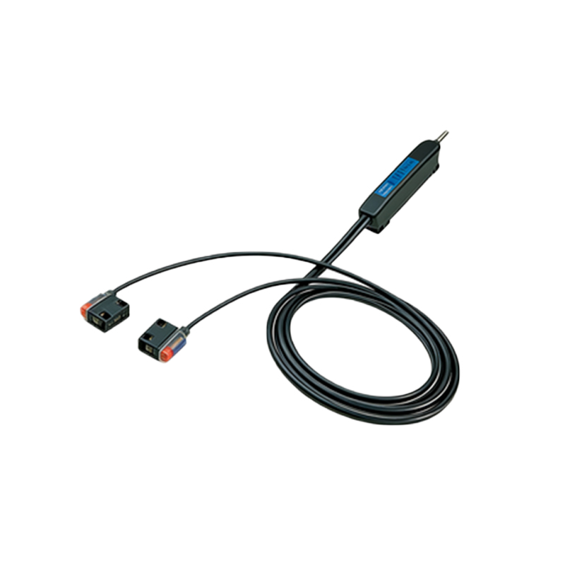
Successful installation begins long before mounting the sensor. Conduct a thorough site assessment to identify potential obstacles and interferences. Key factors include the target object's characteristics (size, color, material, surface texture), the required sensing distance, and the operational environment. Assess for ambient light sources, dust, fog, steam, or vibrations that could affect performance. Ensure the sensor's specifications, such as its housing material (e.g., metal or plastic), ingress protection (IP) rating, and temperature range, are suitable for the application environment. Planning the cable routing path to avoid sharp bends, tension, or areas with high electromagnetic interference is also essential at this stage.
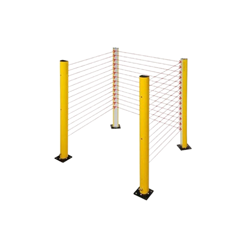
Mechanical Mounting and Alignment Procedures
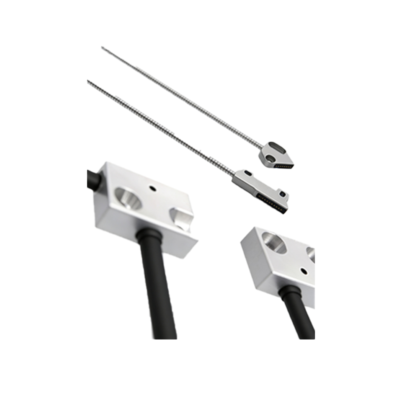
Secure and stable mechanical mounting is paramount. Use the appropriate brackets or mounting hardware provided by the manufacturer. For through-beam sensors, first, securely mount the emitter and receiver units on stable surfaces, ensuring they are perfectly opposite each other. Precise alignment is critical; even a minor angular deviation can cause failure. Many sensors feature built-in alignment indicators (like LED lights that change color or blink when aligned). Utilize these tools during installation. For retro-reflective sensors, ensure the reflector is mounted perpendicular to the sensor's beam axis. Diffuse sensors should be mounted at an optimal angle to the target's expected surface to maximize reflectivity. Always tighten mounting hardware to the specified torque to prevent loosening from vibration.
Electrical Wiring and Connection Guidelines
Adhere strictly to the wiring diagram provided in the sensor's datasheet. Identify the correct wires for power supply, output signal, and any auxiliary functions. Use the recommended wire gauge and ensure all connections are tight and secure. Implement proper grounding techniques to shield the sensor from electrical noise, which is a common cause of erratic operation. For DC sensors, observe correct polarity. It is a best practice to use shielded cables in electrically noisy environments, connecting the shield to ground at only one end (typically the control panel end) to prevent ground loops. Always disconnect power before making or altering any electrical connections to ensure safety.
Configuring Sensitivity and Operational Settings
After physical and electrical installation, configure the sensor for optimal performance. Most modern photoelectric sensors feature a sensitivity adjustment potentiometer or teach-in function. For through-beam and retro-reflective modes, adjust the sensitivity so the sensor operates reliably with the target present, even under worst-case conditions (e.g., dirty lens or low light conditions). For diffuse sensors, sensitivity adjustment is crucial to ignore background objects and only detect the intended target. Set the response time (on/off delay) appropriately for the application speed to prevent false triggering or missed detections. Some sensors offer functions like light-on/dark-on mode selection or short-circuit protection, which should be configured as needed.
Testing, Verification, and Troubleshooting
Comprehensive testing validates the installation. Perform functional tests by introducing the target object repeatedly under normal operating conditions. Verify consistent switching of the output indicator. Test under extreme conditions, such as with dirty or reflective objects nearby, to ensure stability. Common installation-related issues include misalignment, insufficient sensing distance, electrical interference, and environmental factors like condensation on the lens. If problems occur, systematically check alignment, clean the lens and reflector, verify power supply voltage, and inspect wiring. Consult the sensor's manual for specific error indicators and troubleshooting steps.
Implementing Long-Term Maintenance Practices
A proper installation includes planning for maintenance. Establish a regular inspection schedule to check for lens cleanliness, mounting stability, and cable integrity. In dirty environments, periodic cleaning of the lens and reflector with appropriate materials is necessary to maintain optical performance. Keep a log of sensor performance and any adjustments made. Consider the use of protective accessories like sunshades to combat strong ambient light or protective guards to prevent physical damage. Proactive maintenance based on the initial installation best practices significantly extends sensor life and ensures ongoing system reliability.