What is Trigger Frequency?
Trigger frequency, often measured in Hertz (Hz), is a critical performance parameter for inductive, capacitive, and photoelectric proximity sensors. It defines the maximum number of switching operations (ON/OFF cycles) a sensor can reliably perform per second. In essence, it quantifies the sensor's speed—how quickly it can detect a target, send a signal, reset, and be ready to detect the next target. A higher trigger frequency indicates a faster-responding sensor capable of handling high-speed applications. This specification is paramount in automated systems where the speed of object detection directly impacts cycle times, throughput, and overall machine efficiency. Understanding this specification is the first step in selecting the right sensor for any high-speed automation task.
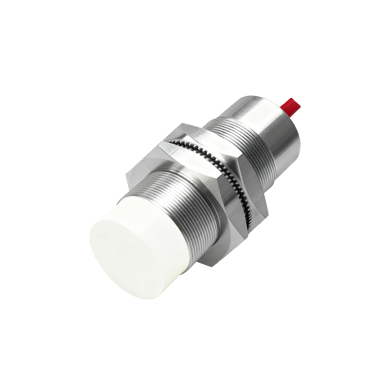
Factors Influencing Maximum Frequency
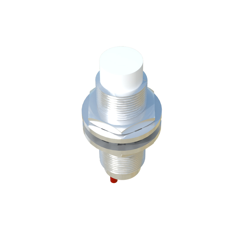
Several key factors determine the maximum achievable trigger frequency of a proximity sensor. The sensor's internal oscillator circuit and signal processing electronics set a fundamental physical limit. The sensing distance also plays a crucial role; operating at the rated nominal sensing distance (Sn) typically yields the best performance. Excessively long mounting distances can reduce frequency. The target material and size are equally important. For inductive sensors, a standard ferrous metal target of recommended size will achieve the published frequency. Smaller targets or non-ferrous metals like aluminum may reduce the effective switching frequency. Finally, the output configuration matters. Two-wire sensors generally have lower maximum frequencies than three-wire DC types due to their inherent leakage current and voltage drop characteristics.
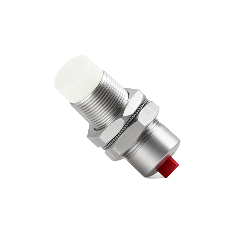
Calculating Frequency for Practical Applications
To ensure a sensor meets application demands, a practical calculation is necessary. The required trigger frequency (f_req) can be estimated by considering the target speed (v) and the target size (d) in the direction of travel. A simplified formula is f_req = v / d. For example, if small components on a conveyor belt are spaced 50mm apart (d=0.05m) and the belt moves at 3 meters per second (v=3 m/s), the required sensing frequency is at least 60 Hz. It is a best practice to select a sensor with a rated maximum frequency at least 1.5 to 2 times higher than this calculated requirement. This safety margin accounts for real-world variables like target alignment, material variations, and ensures reliable operation without missed counts or false triggers under all operating conditions.
Impact of Output Type and Wiring
The choice between PNP/NPN, NO/NC, and two-wire/three-wire configurations significantly impacts performance. Three-wire DC sensors (PNP or NPN) offer the highest trigger frequencies, often ranging from 500 Hz to 5 kHz or more, as they use a transistor output that switches rapidly. Two-wire AC/DC sensors have lower maximum frequencies, typically below 100 Hz, because the switching element must handle the load current directly, leading to slower turn-off times. Furthermore, the wiring length and electrical noise can affect performance. Long cable runs introduce capacitance that can slow down signal edges, effectively reducing the practical switching frequency. Using shielded cables and proper grounding is essential to maintain signal integrity and achieve the sensor's published frequency specs in electrically noisy industrial environments.
High-Frequency vs. Standard Sensors
Manufacturers offer specialized "high-frequency" or "fast-response" proximity sensors designed explicitly for demanding applications. These sensors employ advanced ASIC (Application-Specific Integrated Circuit) technology and optimized coil designs to achieve frequencies of 10 kHz, 20 kHz, or even higher. They are indispensable in packaging machinery, small parts counting, high-speed sorting, and robotic pick-and-place systems. In contrast, standard sensors with frequencies from 10 Hz to 500 Hz are perfectly adequate for slower processes like position detection on indexing tables or door open/close monitoring. Selecting a standard sensor for a high-speed task will result in missed pulses, while using an ultra-high-frequency sensor for a slow application is an unnecessary cost. Matching the sensor's capability to the task is key to cost-effective design.
Ensuring Reliability at High Speeds
Achieving reliable operation at the sensor's maximum rated frequency requires careful installation and setup. First, ensure the target meets the sensor's specifications for material, size, and approach direction. The target should pass directly over the sensing face. Second, adjust the sensor's sensitivity or mounting distance so that the target is well within the reliable sensing range, avoiding the edge of the detection field. Third, consider the sensor's hysteresis—the difference between the switch-on and switch-off points. Adequate hysteresis prevents chattering when a target is present, which is crucial for clean signal output at high frequencies. Regularly cleaning the sensor face from dust, oil, or debris is also vital, as