Introduction to Rotary Proximity Switches
Rotary proximity switches, also known as rotary cam limit switches or rotary position sensors, are essential components in industrial automation and machinery control. These devices are designed to detect the angular position or rotational movement of a shaft, providing precise feedback for controlling processes such as sequencing, positioning, and safety interlocks. Unlike linear proximity sensors that detect straight-line motion, rotary versions are tailored for rotational applications, making them ideal for use in conveyors, indexing tables, cranes, and packaging equipment. Their robust construction allows them to operate reliably in harsh environments with dust, moisture, and temperature variations, ensuring long-term performance in demanding settings.
Core Components and Structure
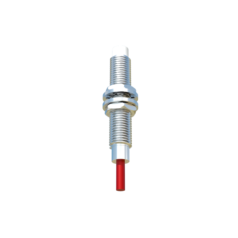
A typical rotary proximity switch consists of several key parts: a rotating shaft, a cam disc or actuator, a sensor head, and an electronic housing. The shaft is connected to the moving part of the machinery, such as a motor or gearbox, and rotates accordingly. Attached to this shaft is a cam disc, which is often adjustable and features lobes or protrusions that trigger the sensor as they pass by. The sensor head, usually based on inductive, capacitive, or magnetic technology, is mounted in a fixed position near the cam disc. Inside the housing, circuitry processes signals from the sensor to generate output signals, such as switching contacts or digital pulses, which interface with control systems like PLCs (Programmable Logic Controllers). This modular design enables easy customization for different angular ranges and switching points.
Operating Principle Based on Sensing Technology
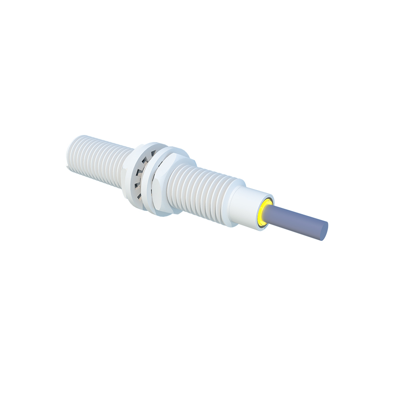
The working principle of a rotary proximity switch hinges on its sensing technology, with inductive and magnetic types being the most common. In an inductive rotary proximity switch, the sensor head contains a coil that generates an oscillating electromagnetic field. When a metallic cam lobe enters this field, eddy currents are induced in the metal, causing a change in the oscillation amplitude. This change is detected by the internal circuitry, which then activates a solid-state switch or relay to send an output signal. Magnetic rotary proximity switches, on the other hand, use a Hall effect or reed sensor paired with a magnet-equipped cam. As the magnet rotates past the sensor, the magnetic field variation triggers a switch, offering contactless operation that is wear-free and suitable for high-speed applications. Both methods provide non-contact detection, eliminating mechanical wear and ensuring high durability.
Signal Output and Interface Mechanisms
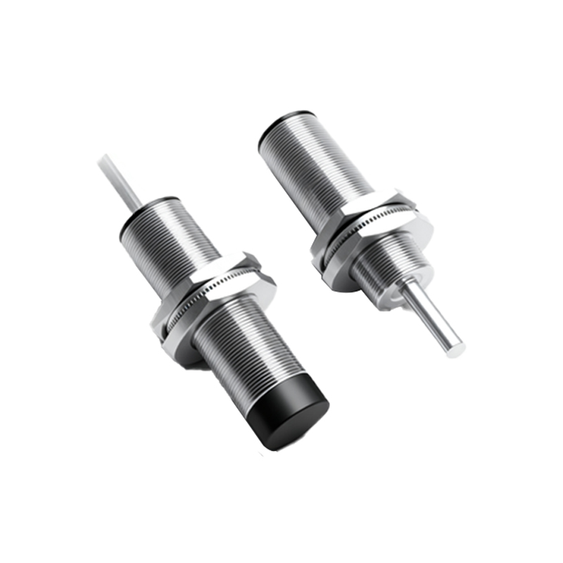
Upon detecting rotational movement, rotary proximity switches convert the positional data into electrical signals for control systems. Common output types include discrete (digital) signals, such as NPN or PNP transistor outputs, which provide simple on/off switching for limit functions. Analog outputs, like 4-20 mA or 0-10 V signals, offer continuous position feedback, enabling precise monitoring of shaft angles. Additionally, some advanced models feature programmable outputs or communication protocols like IO-Link for enhanced data exchange. The interface mechanism often involves adjustable cams that can be set to specific angles, allowing users to define exact switching points for multiple operations within a single rotation. This flexibility supports complex sequencing in automated machinery, where timing and position accuracy are critical.
Applications in Industrial Automation
Rotary proximity switches are widely deployed across various industries due to their reliability and precision. In material handling systems, they monitor conveyor belt rotations to prevent jams or track product flow. For packaging machines, these sensors control the positioning of filling heads or sealing mechanisms, ensuring consistent operation. In crane and hoist equipment, they serve as safety devices by limiting rotational travel to prevent over-winding. Other applications include robotics for joint angle sensing, wind turbines for pitch control, and automotive assembly lines for part alignment. Their ability to withstand vibrations, temperature extremes, and contaminants makes them a preferred choice for harsh industrial environments, contributing to improved efficiency and reduced downtime.
Advantages and Selection Considerations
The primary advantages of rotary proximity switches include non-contact operation, which minimizes wear and maintenance, and high repeatability for accurate position sensing. They also offer fast response times, often in milliseconds, suitable for high-speed machinery. When selecting a rotary proximity switch, engineers should consider factors such as the required sensing range, rotational speed, environmental conditions (e.g., IP rating for dust and water resistance), output type compatibility with existing control systems, and mounting options. Additionally, the material of the cam—typically metal for inductive sensors or magnetic for Hall effect sensors—must match the technology to ensure reliable detection. Proper installation and calibration are crucial to optimize performance and extend service life.
Maintenance and Troubleshooting Tips
To ensure optimal functionality, regular maintenance of rotary proximity switches involves inspecting the sensor head and cam disc