Understanding Photoelectric Sensor Fundamentals
Photoelectric sensors operate by emitting a light beam, typically from an LED or laser diode, and detecting changes in the received light intensity via a phototransistor or photodiode. The core principle involves the interruption, reflection, or absorption of this beam by a target object, which alters the electrical output of the receiver circuit. A basic circuit consists of an emitter section with a current-limiting resistor and a receiver section that converts light into a measurable voltage or current signal. Key parameters include sensing distance, response time, and ambient light immunity. Before any debugging begins, verify the sensor's datasheet for its operational voltage range, output type (digital or analog), and connection diagrams. Incorrect wiring is a primary cause of failure, so always confirm power supply polarity and signal line connections against the manufacturer's specifications.
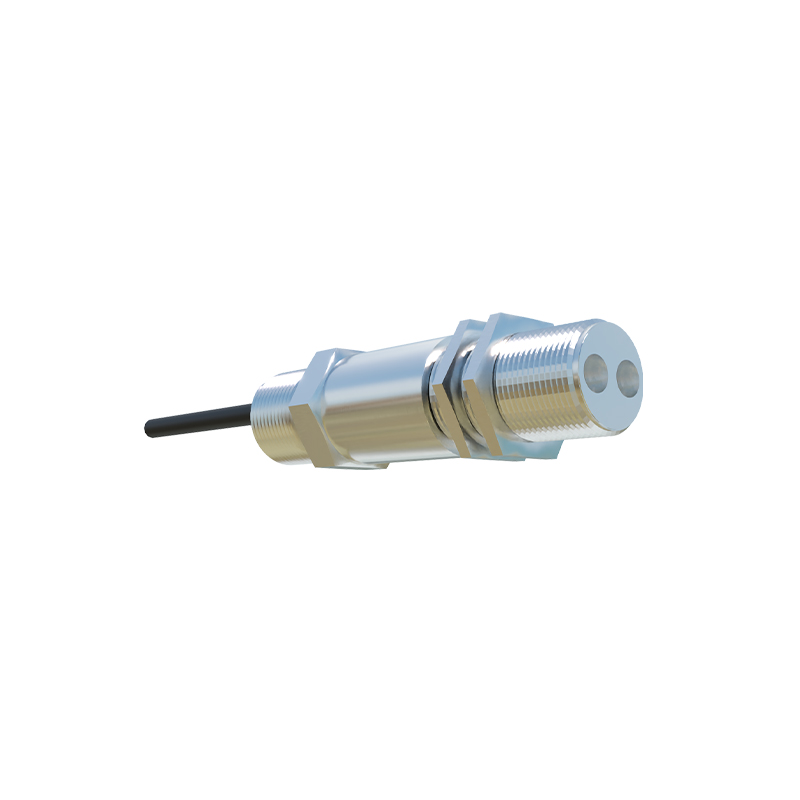
Common Circuit Issues and Initial Checks
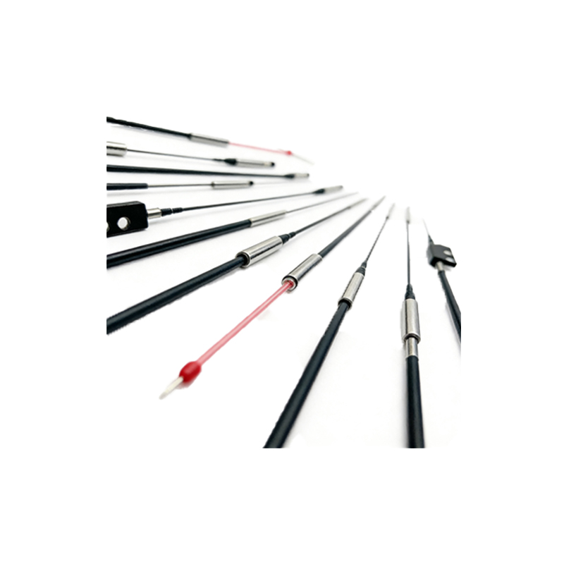
When a photoelectric sensor circuit malfunctions, start with visual and basic electrical inspections. Look for obvious physical damage, loose connectors, or misaligned emitter and receiver lenses. Use a multimeter to check the power supply voltage at the sensor terminals to ensure it is within the specified range, typically 10-30V DC for many industrial models. If the voltage is low or unstable, investigate the power source and wiring for voltage drops or noise. Next, examine the output signal. For a digital (switching) output, measure the voltage between the output wire and ground. A properly triggered sensor should show a clear high or low logic level corresponding to its configuration (NPN sinking or PNP sourcing). An analog output should vary smoothly with target distance or reflectivity. If no output change is observed, the issue may lie in the sensing path or internal components.
Optimizing Alignment and Sensing Conditions
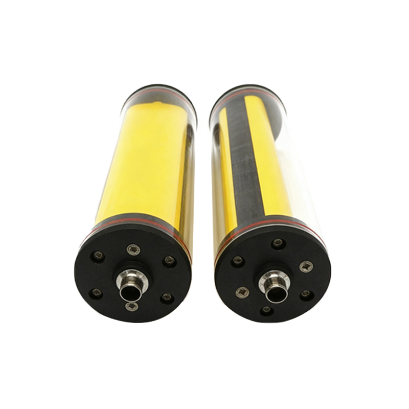
Misalignment is a frequent problem, especially in through-beam (opposed) mode where separate emitter and receiver units must be precisely aligned. Use alignment tools or indicators if provided by the sensor. For reflective modes, ensure the target surface has suitable reflectivity and is within the specified sensing window. Environmental factors like dust, fog, or strong ambient light can interfere. To mitigate this, many sensors feature modulated light (often in the infrared spectrum) and synchronous detection circuits to ignore constant ambient light. Verify that the sensor's modulation frequency is not being disrupted by other electronic equipment. Adjust the sensor's sensitivity potentiometer, if available, to achieve reliable detection without false triggers. A helpful technique is to monitor the receiver's raw signal with an oscilloscope to see the actual light pulse waveform and noise levels.
Analyzing and Resolving Electrical Noise
Electrical noise can cause erratic sensor behavior or reduced sensing range. Noise often enters through power lines, output signal lines, or even radiatively. Implement best practices such as using shielded cables for long runs, with the shield grounded at one end only (usually the controller side). Keep sensor cables away from high-voltage AC lines, motor drives, and other noise sources. Adding a filter capacitor (e.g., 0.1µF ceramic) across the power supply terminals near the sensor can suppress high-frequency noise. For output lines, a small RC filter might be necessary if the connected PLC or counter is sensitive to contact bounce or noise. If using an analog output, averaging or filtering in software may be required. Ground loops can also introduce hum; ensure all grounds are connected to a single point if possible.
Testing with Diagnostic Tools
Advanced debugging requires diagnostic tools. An oscilloscope is invaluable for observing the sensor's internal timing and signal integrity. Probe the emitter drive current to confirm it is pulsating at the correct frequency. On the receiver side, examine the amplified signal before it reaches the output comparator. Many modern sensors have diagnostic LEDs that indicate power status, output activation, and sometimes signal strength. Refer to the manual to interpret these indicators. For programmable sensors, use the manufacturer's software to monitor real-time parameters and adjust settings like hysteresis, time delays, and output inversion. A lux meter or a dedicated sensor tester can measure the actual light intensity received, helping to quantify alignment or lens contamination issues.
Calibration and Long-Term Stability
After resolving immediate issues, focus on calibration and stability. Calibrate the sensor under normal operating conditions with a representative target. For analog sensors, map the output voltage or current to the desired physical parameter (e.g., distance). Establish a maintenance schedule to clean lenses from dust and oil buildup, which gradually attenuate light. Periodically re-check alignment, as vibrations can shift mounts over time. Monitor temperature effects; extreme temperatures can affect LED output and component values. If the sensor is in a critical application, consider implementing a redundancy or monitoring circuit that checks for sensor failure. Document all settings, adjustments, and test results for future reference. A well-debugged and maintained photoelectric sensor circuit should provide reliable, long-term operation with minimal downtime.