Understanding Proximity Sensor Fundamentals
Proximity sensors are indispensable components in modern industrial automation, providing non-contact detection of metallic or other objects. Their primary function is to sense the presence or absence of a target without physical contact, thereby offering high reliability and long operational life. These sensors are widely used in applications ranging from machine safety and position sensing to counting and inspection on assembly lines. The core technology behind inductive proximity sensors, the most common type for metal detection, involves an oscillating circuit that creates an electromagnetic field. When a metallic target enters this field, it induces eddy currents that dampen the oscillation, triggering a change in the sensor's output state. This fundamental principle remains consistent, but the method of connecting the sensor to a control system varies significantly between 2-wire and 3-wire designs, impacting installation, performance, and application suitability.
The 2-Wire Proximity Sensor Configuration
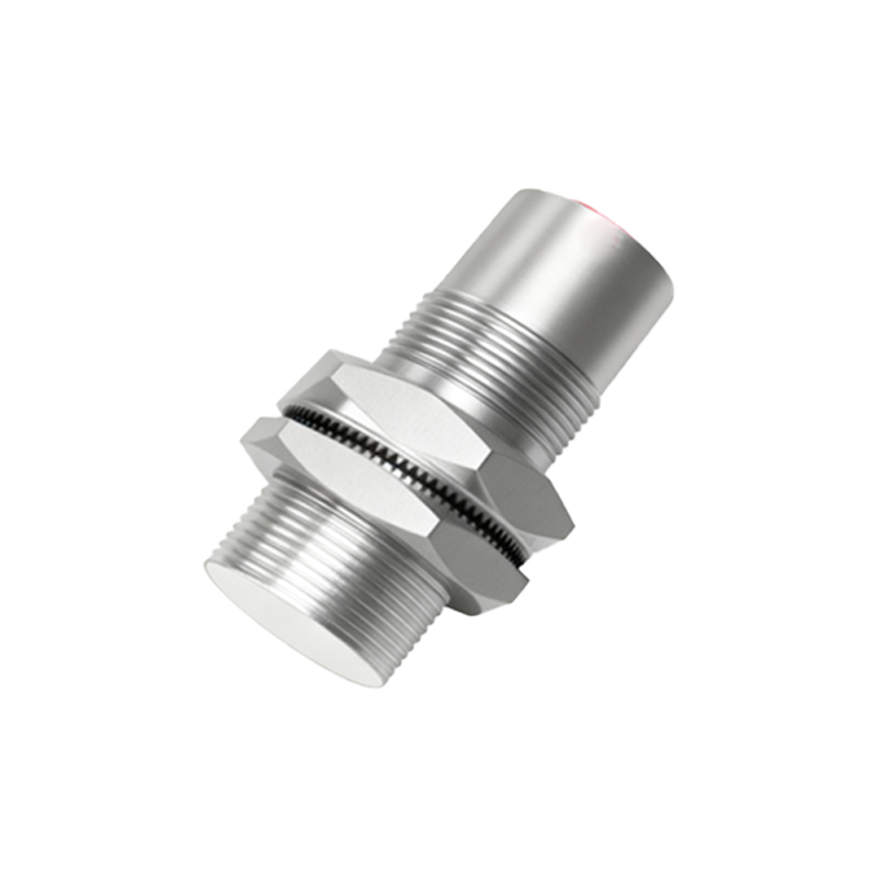
The 2-wire proximity sensor is the simplest in terms of wiring. It connects in series with the load, much like a conventional switch. The two wires handle both the power supply for the sensor's internal electronics and the switching of the load current. In a typical DC circuit, one wire connects to the positive voltage supply, and the other connects to the load, which then connects to ground. When the sensor is inactive (no target detected), a small leakage current, often called residual current, flows through the sensor to power its internal circuitry. Upon detecting a target, the sensor switches on, allowing the full load current to pass through to the actuator, such as a PLC input or a relay coil. A key advantage of the 2-wire system is its straightforward installation and reduced wiring, as it eliminates the need for a separate power connection. However, designers must carefully consider the voltage drop across the sensor and the minimum holding current required for the load, as the leakage current must be below the load's turn-on threshold to prevent false triggering.
The 3-Wire Proximity Sensor Configuration
The 3-wire sensor separates the power supply and output switching functions, leading to more precise and reliable operation. These sensors have three distinct wires: typically a brown wire for the positive supply (V+), a blue wire for the common negative or ground (V-), and a black wire for the switched output signal. The internal electronics are powered directly between the brown and blue wires. The black output wire acts as a switch, connecting either to the positive supply (for a PNP, or sourcing, sensor) or to the ground (for an NPN, or sinking, sensor) when a target is detected. This separation allows the sensor's switching circuit to be completely independent of the load current. Consequently, 3-wire sensors exhibit virtually no leakage current when off and can switch very low-power loads, such as high-impedance PLC inputs, without risk of false activation. They also offer faster switching speeds and are available in both PNP and NPN transistor output types, providing flexibility for different PLC and control system architectures.
Key Differences and Application Considerations
Choosing between a 2-wire and 3-wire proximity sensor hinges on specific application requirements. The 2-wire sensor is often favored for its simplicity, lower initial cost for wiring, and direct replacement capability for mechanical limit switches. It is suitable for applications with higher power loads like contactors, relays, or lamps, where the leakage current is not a critical concern. Its main limitations include a higher voltage drop, sensitivity to electrical noise due to shared paths, and potential issues with low-current loads. In contrast, the 3-wire sensor is the preferred choice for complex control systems, especially those using programmable logic controllers (PLCs). Its advantages include minimal voltage drop, no leakage current, compatibility with low-current sinking or sourcing inputs, superior noise immunity, and generally faster response times. The trade-off is the need for an additional wire, making installation slightly more complex and potentially more costly in terms of cabling.
Installation and Wiring Best Practices
Proper installation is critical for optimal sensor performance and system safety. For 2-wire sensors, always verify that the sensor's leakage current is less than the "Off-state" current requirement of the load. Use shielded cables in electrically noisy environments and ensure the load is within the sensor's specified current ratings. For 3-wire sensors, correctly identifying the PNP (sourcing) or NPN (sinking) type is paramount to match the control system's input card. A common mistake is mixing these types, which can lead to improper circuit operation. Always connect the blue wire to the DC common (0V). For both types, adhere to the specified