Introduction to EV3 Dual Light Sensor Positioning
In the realm of educational and competitive robotics, precise navigation and positioning are paramount. The LEGO Mindstorms EV3 platform provides a versatile suite of sensors, among which the Light Sensor is a critical tool for environmental interaction. While a single light sensor can perform basic line-following tasks, employing a dual light sensor configuration unlocks a higher level of accuracy and reliability in robot positioning. This technique, often referred to as dual or differential light sensor positioning, leverages two sensors mounted side-by-side to detect contrasts on a surface, typically a line or boundary. The core principle involves comparing the reflected light intensity readings from both sensors. This differential data allows the robot's control system, programmed within the EV3 software environment, to make real-time adjustments to its motor power, thereby enabling it to center itself on a line or maintain a specific offset with remarkable precision. This method significantly reduces the oscillatory "wiggle" common in simpler single-sensor proportional algorithms, leading to smoother, faster, and more deterministic movement—a fundamental requirement for complex tasks in robotics challenges.
Hardware Configuration and Calibration
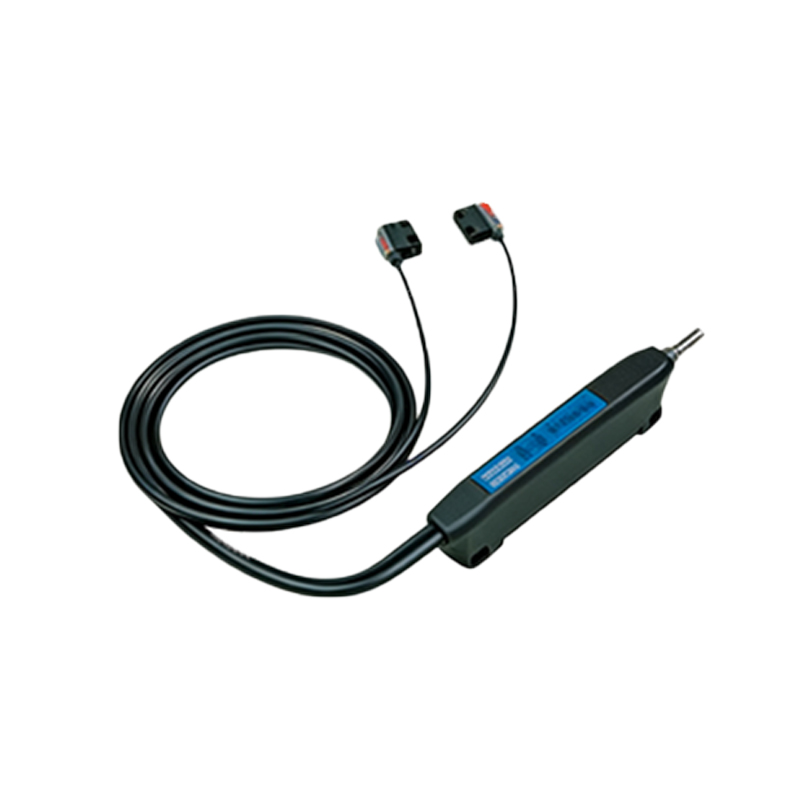
The physical setup is straightforward but requires careful attention to detail. Two EV3 Light Sensors must be attached to the front of the robot, aligned parallel to the direction of travel and spaced appropriately for the target line width. A common spacing is slightly wider than the line itself, allowing each sensor to straddle the edge. Proper mounting rigidity is essential to prevent misalignment during operation. Before deployment, sensor calibration is a non-negotiable step. Ambient light conditions can drastically affect sensor readings. Therefore, a calibration routine should be executed on the actual course surface. This typically involves sampling the minimum (over a dark line) and maximum (over the light surface) values for each sensor individually. These calibrated values are then used to normalize subsequent readings into a percentage scale (0-100%), ensuring consistent performance regardless of minor lighting changes. This process transforms raw sensor data into reliable, actionable input for the control algorithm.
The Core Positioning Algorithm
The intelligence of this system resides in its algorithm. The most effective approach is a Proportional-Integral-Derivative (PID) controller, though a simpler Proportional (P) or Proportional-Derivative (PD) controller often suffices for many applications. The algorithm continuously calculates an "error" value. This error is derived from the difference between the two sensors' normalized readings. For instance, if the robot is perfectly centered on a black line, both sensors may read similar mid-range values (e.g., 50% on the line edge), resulting in an error near zero. If the robot drifts to the left, the left sensor will detect more darkness (lower percentage) and the right sensor more lightness (higher percentage), generating a positive error value. This error is fed into the PID formula. The Proportional term provides an immediate corrective response proportional to the error. The Derivative term considers the rate of error change, damping the system to prevent overshoot and oscillation. The Integral term addresses accumulated small errors over time, correcting for systematic drift. The output of the PID calculation is a steering correction, often applied as a power differential to the left and right drive motors.
Programming Implementation in EV3 Software
Implementing this logic within the EV3 programming environment, whether using the graphical blocks or a text-based language like EV3-G or Python, follows a clear structure. The program initiates with calibration sequences. The main control loop then begins, executing at a high frequency. Within each loop cycle, the program: 1) Reads the current reflected light intensity from both sensors. 2) Normalizes these readings using the stored calibration data. 3) Calculates the instantaneous error (e.g., Right Sensor Value - Left Sensor Value). 4) Computes the PID control value. Tuning the PID constants (Kp, Ki, Kd) is an iterative process of testing and adjustment to achieve a responsive yet stable movement. 5) Applies the control value by setting motor powers. A common method is to calculate a base power for both motors and then add the control value to one side and subtract it from the other. The loop repeats indefinitely, creating a closed-feedback system that constantly corrects the robot's path.
Advanced Applications and Optimizations
Beyond simple line centering, dual light sensor positioning forms the foundation for sophisticated navigation. One advanced application is grid following, where robots use intersecting lines to navigate a coordinate system. By counting line crossings and integrating data from rotation sensors, the robot can dead-reckon its position on a grid with high accuracy. Another optimization involves dynamic thresholding for handling curves of varying sharpness or faded line markings. The algorithm can be enhanced to adjust its PID constants or base speed based on the magnitude of the error, allowing for slower, more careful navigation on tight turns. Furthermore, the sensors can be used for detecting features like junctions, where a specific signature in the sensor data (e.g., both sensors seeing dark simultaneously) triggers a predefined maneuver, such as a turn or a stop. This transforms the robot from a simple line follower into an autonomous agent capable of making decisions based on its perceived location.
Troubleshooting Common Issues
Despite its robustness, practitioners may encounter issues. Erratic behavior often stems from poor calibration; re-calibrating under current lighting conditions is the first step. Mechanical issues, such as loose sensor mounts or uneven tire pressure, can introduce noise and inconsistency. Electrical interference or low battery levels can also cause sensor reading fluctuations. In the algorithm, an overly high Proportional gain (Kp) causes violent oscillation, while a too-low gain results in sluggish correction and drifting off the line. Excessive Derivative gain can make the system jittery. If using an Integral term, "integral windup" can occur during prolonged large errors (e.g., lifting the robot off the line), causing a large overshoot when the error is corrected; implementing limits on the integral term mitigates this. Systematic testing—adjusting one parameter at a time and observing the robot's behavior on both straight sections and curves—is key to refining performance.
Conclusion and Best Practices
The EV3 dual light sensor positioning technique is a cornerstone of precise robotic navigation. It exemplifies fundamental engineering principles of feedback control, sensor integration, and system tuning. For optimal results, adhere to best practices: ensure a solid mechanical build, perform thorough and repeated calibration, start with a simple P controller and gradually introduce D and I terms as needed, and test extensively on the actual course. Mastering this method not only leads to success in robotics competitions but also provides a deep, practical understanding of control theory, a skill highly transferable to broader fields of engineering and automation. The journey from a wobbling, single-sensor robot to a smoothly gliding, dual-sensor machine is a profound demonstration of the power of precise measurement and intelligent feedback.