Understanding the Core Principle
Capacitive proximity sensors operate on the fundamental principle of capacitance change. At their heart is an oscillator circuit that generates an electrostatic field from the sensing face, which acts as one plate of a capacitor. The target object serves as the other plate. When a target enters this electrostatic field, it alters the dielectric constant and the capacitance of the system. This change in capacitance affects the oscillator's amplitude. An evaluation circuit within the sensor detects this amplitude shift and triggers a solid-state output switch, signaling the presence of the target. Unlike inductive sensors, which detect only metals, capacitive sensors can detect a vast range of materials, including liquids, powders, plastics, wood, and glass, making them exceptionally versatile.
Key Components and Internal Architecture
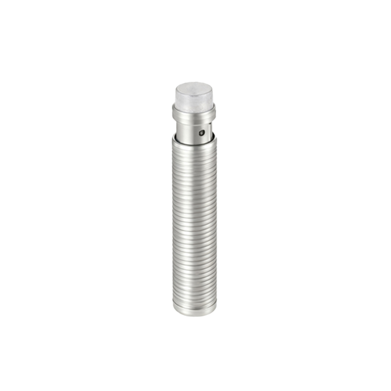
A standard capacitive proximity sensor comprises several critical components. The sensing electrode is the primary element, creating the electrostatic field. It is often surrounded by a guard electrode that shapes and focuses the field, minimizing the influence of the sensor's housing and improving stability. The high-frequency oscillator generates the sensing field, while the demodulator converts the amplitude changes into a DC signal. The trigger circuit compares this signal to a predefined threshold, and the output stage (typically NPN, PNP, or analog) provides the switching signal. The housing is designed to protect these sensitive electronics from environmental factors like dust, moisture, and chemical exposure, with common ingress protection ratings being IP67 and IP69K.
Primary Advantages in Industrial Settings
The most significant advantage of capacitive sensors is their material-agnostic detection capability. This allows for applications impossible for other sensor types, such as monitoring fill levels of non-conductive liquids in tanks or detecting the presence of plastic caps on bottles. They offer excellent stability and are largely unaffected by target color, surface texture, or reflectivity. Modern capacitive sensors feature adjustable sensitivity, often via a potentiometer or teach-in function, allowing fine-tuning to ignore unwanted background objects like container walls. Their solid-state design ensures long operational life with no moving parts to wear out.
Common Industrial Applications and Use Cases
Capacitive proximity sensors find widespread use across numerous industries. In packaging, they detect the presence of cardboard, plastic films, or glass containers on conveyor lines. In the food and beverage sector, they are indispensable for liquid level control in stainless steel or plastic tanks, ensuring precise filling operations. Woodworking and paper processing industries utilize them to monitor material presence and roll diameter. A critical application is in the chemical and pharmaceutical industries, where they can detect powders or granules through non-metallic vessel walls, enabling non-contact, hygienic process control. They are also used in assembly verification, ensuring all components, even non-metallic ones, are present.
Critical Selection Criteria for Engineers
Selecting the right capacitive sensor requires careful consideration of several parameters. The sensing distance, or nominal range, is specified for a standard target (often steel). For non-standard materials, a reduction factor must be applied. The housing material (e.g., PBT, stainless steel) must be compatible with the chemical environment. The output type (NO/NC, NPN/PNP, analog 4-20mA/0-10V) must match the control system's input requirements. Environmental ratings for temperature, pressure, and ingress protection (IP) are crucial. For challenging applications, specialized models with extended ranges, high-temperature tolerance, or enhanced resistance to aggressive media are available.
Installation and Commissioning Best Practices
Proper installation is key to reliable operation. Sensors must be mounted securely to prevent vibration-induced false triggers. A critical rule is to maintain adequate clearance from surrounding metal objects, as specified in the datasheet, to prevent shielding and false actuation. For level detection, the sensor should be mounted such that the sensing field penetrates the tank wall or is in direct contact with the medium, depending on the model. During commissioning, the sensitivity should be adjusted with the target in the desired detection position, then slightly reduced to create a safety margin against environmental drift, such as condensation or material buildup on the sensing face.
Troubleshooting Typical Operational Issues
Common issues with capacitive sensors often stem from installation or environmental factors. Unstable switching may be caused by a fluctuating supply voltage, excessive sensor-to-target distance, or a target material with a very low dielectric constant. False triggers can occur due to material buildup on the sensing face, high humidity, or interference from adjacent sensors or power lines. Solutions include cleaning the sensor face, verifying power supply stability, re-adjusting sensitivity with a margin, ensuring proper grounding, and increasing the separation distance between multiple sensors. Consulting the sensor's diagnostic LEDs, which indicate power status and output