Introduction to Proximity Switch Sensors in Conveyor Systems
Proximity switch sensors are critical components in modern conveyor belt systems, providing non-contact detection of objects or positions. These sensors enhance automation, safety, and efficiency by signaling the presence or absence of materials, enabling precise control over conveyor operations. Commonly used types include inductive, capacitive, and photoelectric sensors, each suited for specific applications based on material properties and environmental conditions. Understanding their wiring is essential for proper installation, maintenance, and troubleshooting in industrial settings. This guide focuses on standard wiring practices for conveyor belt proximity sensors, ensuring reliable performance and compliance with safety standards.
Types of Proximity Sensors and Their Applications
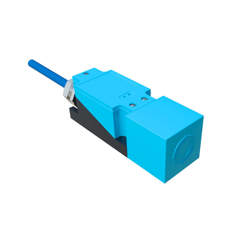
Inductive proximity sensors detect metallic objects without physical contact, making them ideal for conveyor belts handling metal parts or containers. They operate by generating an electromagnetic field and are resistant to dust, dirt, and moisture. Capacitive sensors can detect both metallic and non-metallic materials, such as plastics or liquids, useful in diverse conveyor applications like packaging or food processing. Photoelectric sensors use light beams to sense objects, offering long-range detection for high-speed conveyors. Selecting the right sensor type depends on factors like material composition, conveyor speed, and environmental conditions, which directly influence wiring requirements and system integration.
Basic Wiring Components and Tools Required
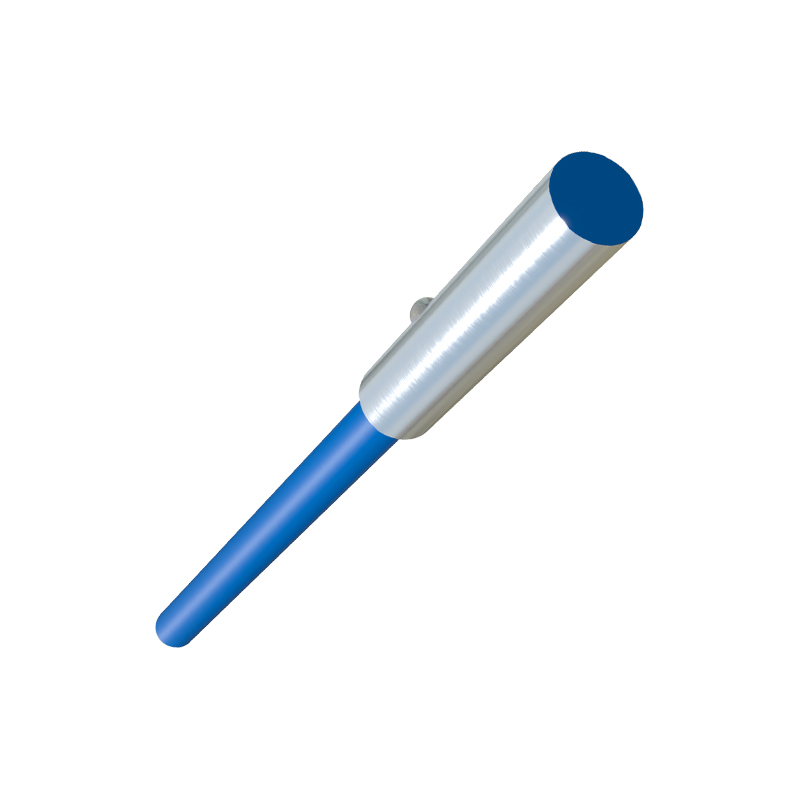
Wiring a proximity switch sensor involves several key components: the sensor itself, a power supply (typically 12-24V DC or 110-230V AC), a controller (e.g., PLC or relay), and connecting cables. Essential tools include wire strippers, screwdrivers, multimeters for testing, and insulation materials. Always refer to the sensor's datasheet for specific voltage, current, and wiring details. Safety gear like gloves and goggles is recommended to prevent electrical hazards. Proper preparation ensures accurate connections, reduces downtime, and minimizes risks of short circuits or sensor damage during installation.
Standard Wiring Diagram for DC Proximity Sensors
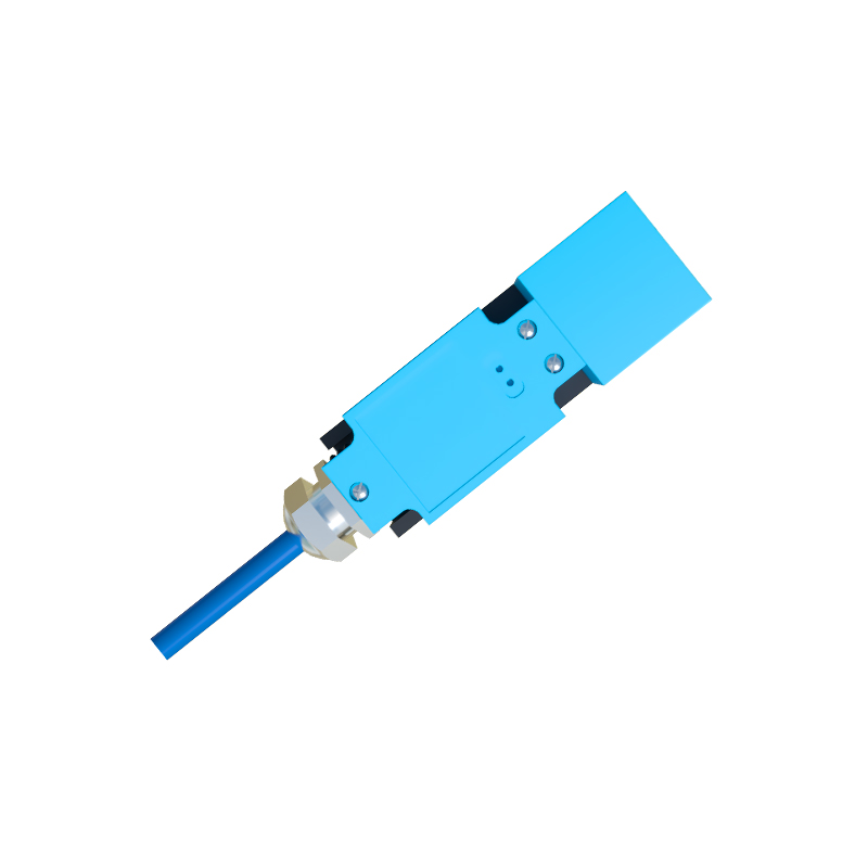
Most conveyor systems use DC proximity sensors for their low power consumption and compatibility with programmable logic controllers (PLCs). A typical 3-wire DC sensor includes brown (positive), blue (negative), and black (output) wires. Connect the brown wire to the positive terminal of the power supply (e.g., +24V), and the blue wire to the negative terminal (0V). The black output wire links to the PLC input or relay, completing the circuit when the sensor detects an object. For 2-wire DC sensors, wiring is simpler: one wire connects to power, and the other to the load, but ensure the load matches the sensor's specifications to avoid malfunction. Always verify polarity and use shielded cables in noisy environments to prevent interference.
Wiring AC Proximity Sensors in Conveyor Setups
AC proximity sensors are less common but used in high-power conveyor applications. They typically have two wires: one for live (AC line) and one for load connection. Wire the live wire to the AC power source (e.g., 110V AC) and the load wire to the control device. Since AC sensors can generate more heat and noise, ensure proper insulation and grounding. Incorporate a fuse or circuit breaker for overload protection. Test the sensor with a multimeter to confirm voltage levels before full operation. Note that AC wiring may require additional safety measures due to higher voltage risks, so follow local electrical codes and manufacturer guidelines strictly.
Connecting Sensors to PLCs and Control Systems
Integrating proximity sensors with PLCs is crucial for automated conveyor control. For DC sensors, connect the output wire to a digital input module on the PLC. Program the PLC to monitor this input and trigger actions like stopping or starting the conveyor belt. Use separate power supplies for sensors and PLCs to avoid ground loops. Label all wires clearly and document connections for future reference. In complex systems, consider using junction boxes or terminal blocks to organize wiring. Regular testing with simulation software can help verify logic and prevent errors in conveyor sequencing or safety interlocks.
Troubleshooting Common Wiring Issues
Common wiring problems in conveyor proximity sensors include incorrect voltage, loose connections, or environmental interference. If a sensor fails to detect objects, check power supply levels with a multimeter and inspect wires for damage. Ensure cables are not near high-voltage lines to avoid electromagnetic interference. For false triggers, verify grounding and shield connections. Consult the sensor's LED indicators (if available) for status clues. Regular maintenance, such as cleaning sensor faces and tightening terminals, can prevent issues. Keep wiring diagrams accessible to speed up repairs and reduce conveyor downtime.