Introduction to KS-C2G Photoelectric Sensor
The KS-C2G photoelectric sensor is a versatile and reliable device widely used in industrial automation for object detection, positioning, and counting applications. Designed with advanced optical technology, it offers high precision and stability in various environmental conditions. This sensor operates by emitting a light beam and detecting changes in the received light intensity, making it suitable for detecting objects regardless of material, color, or surface texture. Its compact design and robust construction ensure durability in harsh industrial settings, such as manufacturing lines, packaging systems, and material handling equipment. Understanding the wiring of the KS-C2G is crucial for proper installation and optimal performance, as incorrect connections can lead to malfunctions or damage. This guide provides a detailed, step-by-step explanation of the wiring process, ensuring safe and efficient integration into your control systems.
Key Components and Specifications
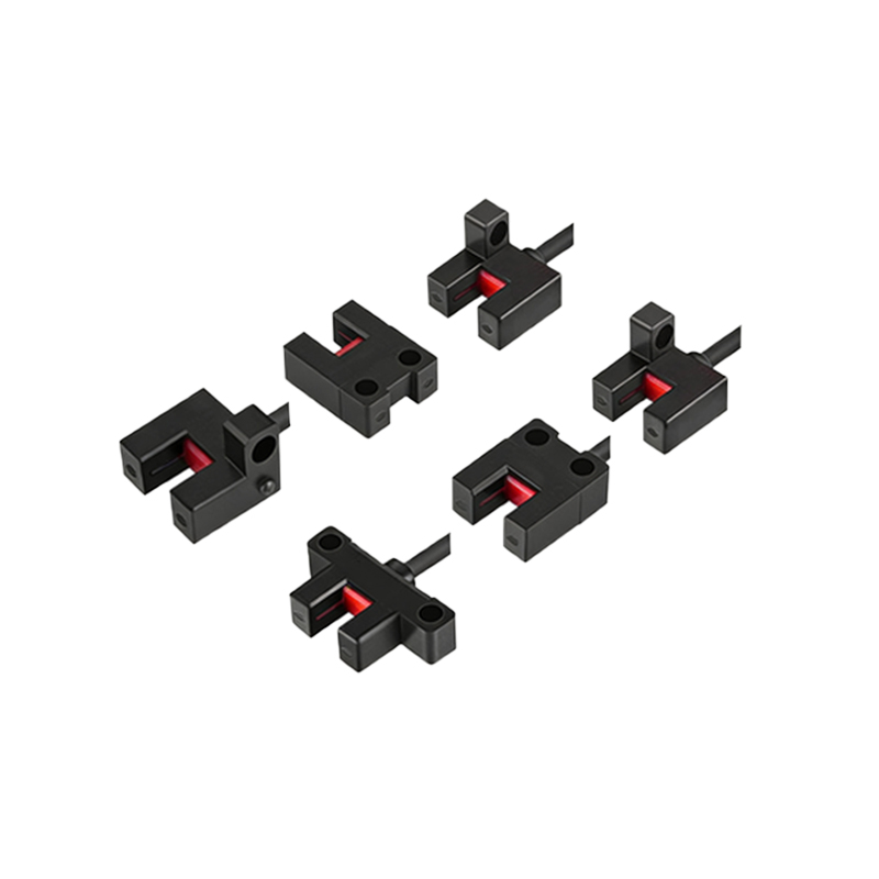
Before proceeding with wiring, familiarize yourself with the key components and specifications of the KS-C2G sensor. It typically includes a housing with an emitter and receiver, connection terminals, and status indicators. The sensor operates on a DC voltage range, commonly 12-24V DC, and features output types such as NPN or PNP transistor outputs, depending on the model. It may also have adjustable sensitivity and response time settings to customize detection performance. The connection terminals are usually labeled for easy identification: V+ (positive power supply), V- (negative power supply or ground), and OUT (output signal). Additionally, some models include protective functions like short-circuit and reverse polarity protection to enhance safety. Refer to the manufacturer's datasheet for specific details, as variations can exist between different versions or batches.
Safety Precautions Before Wiring
Safety is paramount when working with electrical devices like the KS-C2G sensor. Always disconnect power to the control circuit before starting any wiring work to prevent electric shock or equipment damage. Use appropriate personal protective equipment, such as insulated gloves and safety glasses, especially in industrial environments. Ensure the work area is dry and free from flammable materials. Verify the sensor's voltage rating matches your power supply to avoid overvoltage issues that could cause overheating or failure. Double-check all connections against the wiring diagram provided in the sensor's manual, and avoid loose or exposed wires that might lead to short circuits. If unsure, consult a qualified electrician or the manufacturer's technical support for assistance.
Wiring Diagram and Terminal Functions
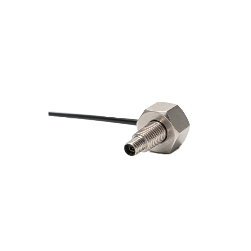
A clear wiring diagram is essential for correct installation. For the KS-C2G sensor, the terminals are typically arranged in a standard configuration. The V+ terminal connects to the positive side of the DC power supply, while the V- terminal connects to the negative side or ground. The OUT terminal links to the input of a controller, such as a PLC (Programmable Logic Controller) or relay, to transmit detection signals. If the sensor has additional features like a teach-in function or diagnostic outputs, refer to the specific labels for those terminals. For example, some models include a brown wire for V+, blue for V-, and black for OUT, following common industrial color codes. Always use shielded cables for longer runs to minimize electrical noise interference, and secure connections with proper terminals or connectors to ensure reliability.
Step-by-Step Wiring Instructions
Begin by preparing the necessary tools: wire strippers, screwdrivers, and a multimeter for testing. First, strip about 5-7 mm of insulation from the ends of the power and signal wires. Connect the positive wire from the DC power supply to the V+ terminal on the sensor, tightening the screw securely. Next, attach the negative wire to the V- terminal. Then, connect the output wire from the OUT terminal to the designated input point on your control device. Ensure all connections are firm to prevent arcing or disconnection during operation. After wiring, inspect for any crossed or loose wires. Once verified, apply power gradually and observe the sensor's status LED; a steady or blinking light usually indicates normal operation. Test the detection function by placing an object within range to confirm the output signal triggers correctly.
Testing and Troubleshooting Common Issues
After wiring, thorough testing is crucial to ensure the KS-C2G sensor functions as intended. Use a multimeter to check voltage levels at the terminals, confirming they match the specified range. If the sensor fails to detect objects, verify the alignment of the emitter and receiver, as misalignment can reduce sensitivity. Adjust the sensitivity potentiometer if available, and ensure the detection range suits the application. Common issues include no output signal, which may stem from incorrect power connections or a faulty sensor, and intermittent operation, often caused by electrical noise or loose wiring. In such cases, recheck all connections, replace damaged cables, or install noise filters. Consult the troubleshooting section of the manual for model-specific guidance, and consider environmental factors like dust or moisture that might affect performance.
Maintenance and Best Practices
To maintain optimal performance of the KS-C2G sensor, implement regular maintenance routines. Periodically clean the lens surfaces with a soft, dry cloth to prevent dirt buildup that could impair light transmission. Check wiring integrity during routine inspections, looking for signs of wear, corrosion, or loose terminals. Avoid exposing the sensor to extreme temperatures or direct sunlight beyond its rated specifications, as this can degrade components. When integrating multiple sensors, ensure adequate spacing to prevent crosstalk between beams. Follow industry best practices, such as labeling wires and documenting connections for future reference. By adhering to these guidelines, you can extend the sensor's lifespan and reduce downtime in automated systems, enhancing overall productivity and safety.