Introduction to Inductive Proximity Sensors
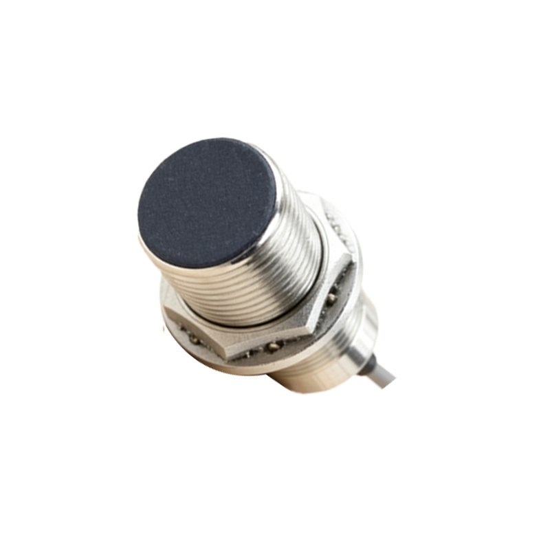
Inductive proximity sensors are non-contact electronic devices designed to detect metallic objects within their sensing range. Operating on the principle of electromagnetic induction, these sensors generate an oscillating electromagnetic field. When a metallic target enters this field, eddy currents are induced in the object, causing a change in the sensor's oscillation amplitude. This change is detected and converted into a switching signal. Widely used in industrial automation, manufacturing, and robotics, these sensors are valued for their robustness, high switching frequency, and immunity to environmental factors like dust, oil, and moisture. Their ability to function without physical contact ensures minimal wear and tear, leading to enhanced reliability and longevity in demanding applications.
Key Parameters and Technical Specifications
Understanding the technical specifications is crucial for selecting the right inductive proximity sensor. Key parameters include sensing distance, which typically ranges from a few millimeters to several centimeters, depending on the sensor size and target material. The nominal sensing distance is usually specified for mild steel; for other metals like aluminum or copper, a correction factor must be applied. Operating voltage is another critical factor, with common ranges being 10-30V DC or 20-250V AC. Output types include NPN, PNP, analog, or IO-Link configurations, each suited for different control systems. Additional specifications to consider are switching frequency (how fast the sensor can detect objects), housing material (often stainless steel or nickel-plated brass for durability), and protection ratings such as IP67 or IP69K for resistance to water and dust.
Importance of Downloadable Resources
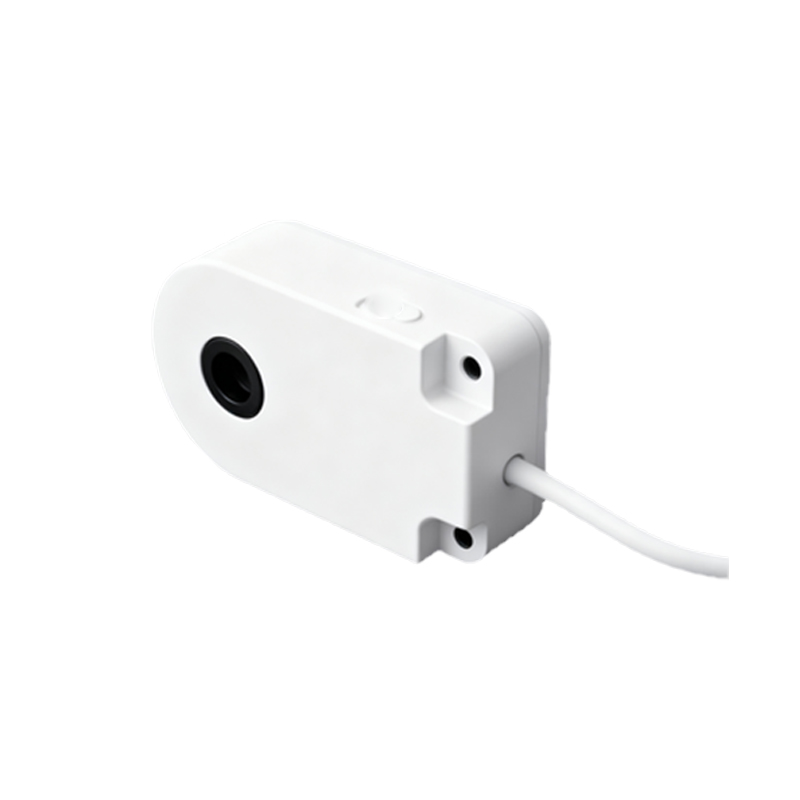
In today's digital engineering environment, access to downloadable resources is essential for efficient design, installation, and maintenance. These resources include datasheets, technical manuals, CAD models, configuration software, and firmware updates. Datasheets provide detailed specifications, wiring diagrams, and dimensional drawings, enabling engineers to verify compatibility with their applications. CAD models, available in formats like STEP or DWG, allow for precise integration into mechanical designs, reducing prototyping errors. Configuration tools and software facilitate parameter setting and diagnostics, especially for smart sensors with IO-Link capabilities. Firmware updates ensure sensors operate with the latest features and bug fixes, enhancing system performance and security.
Types of Downloads Available
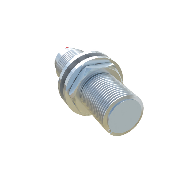
Manufacturers and suppliers typically offer a variety of downloadable files for inductive proximity sensors. Datasheets are the most fundamental, containing all necessary electrical and mechanical data. 2D and 3D CAD models are crucial for design engineers, providing accurate outlines for panel cutouts and mounting arrangements. Instruction manuals offer step-by-step guidance on installation, wiring, and troubleshooting. Application notes and white papers delve into specific use cases, such as high-speed counting or weld-field immunity, offering practical insights. Additionally, software tools like configuration suites or simulation programs may be available for advanced sensor programming. Some platforms also provide mobile apps for on-the-go access to documentation.
How to Access and Utilize Sensor Downloads
To access these resources, visit the manufacturer's official website and navigate to the product support or download section. Use the specific model number or series name to locate relevant files. Ensure you download the latest versions, as specifications may be updated. When utilizing CAD models, import them into your design software to check for interferences and alignment. For configuration files, follow the provided instructions to upload parameters to the sensor using appropriate interfaces like USB or IO-Link. Always cross-reference datasheet information with your system requirements, paying attention to voltage tolerances, temperature ranges, and output compatibility. Organizing downloaded files in a structured digital library can streamline future projects and maintenance tasks.
Best Practices for Implementation
Successful implementation of inductive proximity sensors relies on careful planning and adherence to best practices. First, ensure the sensor is mounted correctly, considering factors like flush or non-flush installation, which affects the sensing distance. Maintain adequate clearance from other metal objects to prevent false triggering. Use shielded cables in electrically noisy environments to minimize interference. Regularly consult downloaded documentation for calibration and diagnostic procedures, especially when integrating sensors into complex automation networks like PLCs or PACs. Perform routine checks using manufacturer-recommended tools to monitor sensor health and preempt failures. Keeping firmware and software updated as per download releases can also optimize performance and add new functionalities over time.
Future Trends and Digital Integration
The evolution of inductive proximity sensors is increasingly tied to digitalization and Industry 4.0. Future trends include enhanced connectivity through IO-Link, enabling real-time data exchange and remote monitoring. Downloads may expand to include APIs for integration with IoT platforms or cloud-based analytics tools. Predictive maintenance features, supported by downloadable algorithms,