Introduction to Photoelectric Sensor Wiring
In industrial automation, photoelectric sensors are pivotal for detecting objects, measuring distances, and ensuring process control. Typically, wiring for these sensors follows conventional color codes: brown for positive voltage, blue for negative or common, black for output signal, and white for complementary functions. However, as sensor technology evolves and applications diversify, less common wire colors such as gray, yellow, purple, orange, and pink have emerged. These colors often denote specialized functions or are tailored to specific manufacturer standards, making them crucial for precise installation and troubleshooting. Understanding these uncommon wire colors enhances system reliability and prevents operational errors in complex setups.
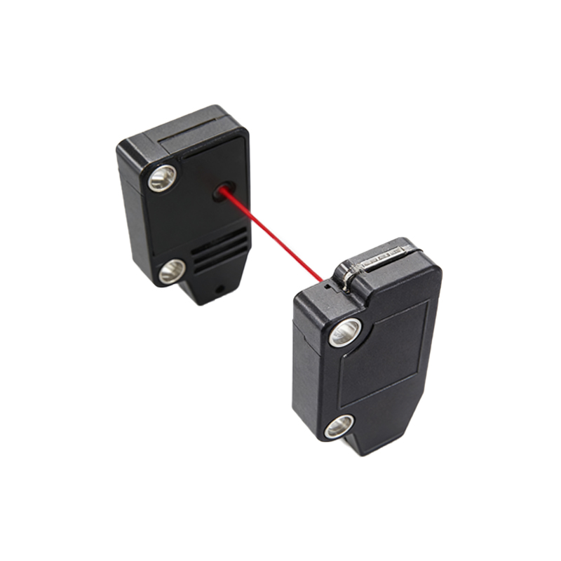
Gray Wires: Auxiliary Outputs and Configuration
Gray wires in photoelectric sensors are frequently associated with auxiliary outputs or configuration modes. Unlike the primary black output wire, a gray wire might indicate a second output channel, often used for dual-signal applications or fail-safe mechanisms. For instance, in sensors with programmable logic, gray wires can enable mode selection, such as switching between light-on and dark-on operations. In some European or custom-designed sensors, gray may serve as a diagnostic line, transmitting status signals for maintenance alerts. Misinterpreting gray wires as neutral lines can lead to incorrect wiring, causing sensor malfunctions or safety hazards. Always refer to the manufacturer’s datasheet to confirm the specific role of gray wires in your sensor model.
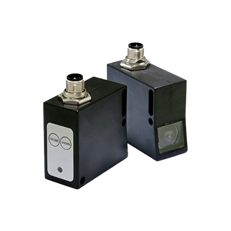
Yellow Wires: Timing and Synchronization Functions
Yellow wires are less common but play a vital role in timing and synchronization within photoelectric sensor systems. They often connect to external timing circuits or control units to coordinate sensor actions with other machinery. For example, in high-speed packaging lines, a yellow wire might trigger a delay function, ensuring precise object detection before activation. Some sensors use yellow for teach-in functions, allowing quick calibration via external inputs. In safety-rated sensors, yellow can indicate an interlock or monitoring circuit, crucial for compliance with international standards like ISO 13849. Ignoring yellow wires may disrupt synchronized operations, leading to production inefficiencies or equipment damage.
Purple Wires: Analog and Specialized Signals
Purple wires typically handle analog signals or specialized communications in advanced photoelectric sensors. Unlike digital black wires, purple wires often transmit analog voltage or current outputs, such as 0-10V or 4-20mA signals, for continuous measurement tasks like distance sensing or opacity detection. In networked sensors, purple might be used for IO-Link or other industrial protocol connections, enabling data exchange for Industry 4.0 applications. Rarely, purple serves as a shield or drain wire for noise reduction in sensitive environments. Confusing purple with power wires can cause signal interference or sensor failure, so verify its function in technical documentation before integration.
Orange and Pink Wires: Custom and Diagnostic Features
Orange and pink wires are among the rarest in photoelectric sensors, usually reserved for custom or diagnostic purposes. Orange wires often denote manufacturer-specific functions, such as external reset inputs or power-saving modes. In some cases, orange indicates a test point for field calibration without disassembling the sensor. Pink wires, though uncommon, might be used for advanced diagnostics, like output inversion or fault indication in smart sensors. These colors are more prevalent in proprietary systems or specialized industries, such as aerospace or medical device manufacturing. Overlooking orange or pink wires can hinder troubleshooting efforts, so engineers should treat them as critical components in complex installations.
Best Practices for Handling Uncommon Wire Colors
To avoid errors with uncommon wire colors, adhere to industry best practices. First, always consult the sensor’s manual or datasheet for accurate color-code definitions, as standards vary by region and brand. Use labeled diagrams during installation and maintenance to track wire functions. For custom-colored wires, document their purposes in system logs for future reference. When replacing sensors, ensure compatibility by matching wire colors and functions, even if they differ from standard codes. Training personnel on these nuances reduces downtime and enhances safety. Ultimately, treating uncommon wire colors as integral to sensor performance fosters efficient automation systems.
Conclusion: Embracing Wiring Diversity in Automation
Uncommon wire colors in photoelectric sensors reflect the innovation and customization driving modern industrial automation. While traditional colors provide a baseline, gray, yellow, purple, orange, and pink wires enable advanced functionalities like dual outputs, timing, analog signals, and diagnostics. Engineers must prioritize accurate interpretation through manufacturer guidelines to leverage these features effectively. As sensors become more intelligent and interconnected, understanding wiring diversity will be key to optimizing productivity and maintaining robust operations. Embrace these variations as opportunities to enhance system capabilities rather than as complexities to avoid.