Understanding Proximity Sensor Fundamentals
Before initiating the debugging process, a solid grasp of proximity sensor fundamentals is essential. Proximity sensors are non-contact devices designed to detect the presence or absence of an object within a specified sensing range. Common types include inductive sensors for metallic objects, capacitive sensors for both metallic and non-metallic materials, and photoelectric sensors using light beams. Each type operates on distinct physical principles—inductive sensors generate an electromagnetic field, capacitive sensors detect changes in capacitance, and photoelectric sensors rely on light interruption or reflection. Understanding the specific sensor type, its nominal sensing distance (Sn), operating voltage, output configuration (PNP/NPN, NO/NC), and environmental ratings is the critical first step. Misapplication, such as using an inductive sensor to detect plastic, is a primary source of failure and must be ruled out before procedural debugging begins.
Pre-Debugging Checklist and Safety
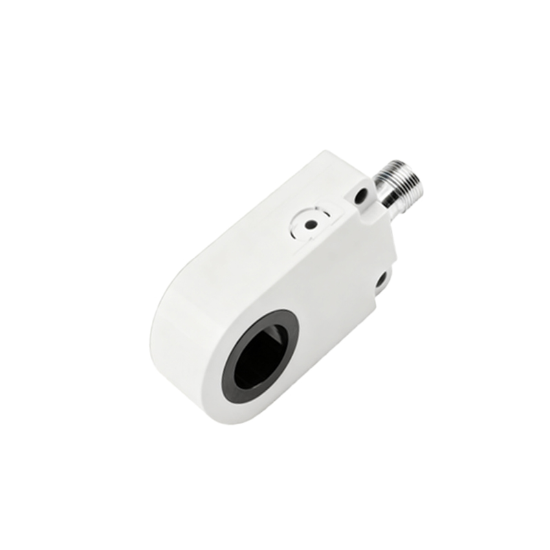
A systematic approach begins with a comprehensive pre-debugging checklist. First, ensure all power is locked out and tagged out (LOTO) before performing any physical inspections or wiring checks. Visually inspect the sensor for any signs of physical damage, corrosion, or contamination. Verify the installation: ensure the sensor is securely mounted, correctly aligned with the target, and that the target object is within the specified sensing range and meets the sensor's material and size requirements. Confirm the electrical connections against the datasheet. Check for proper wiring of the power supply (typically 10-30V DC), load (e.g., PLC input, relay), and ground. A common error is confusing PNP (sourcing) and NPN (sinking) wiring configurations, which can lead to improper operation.
Power and Signal Verification
After confirming safe conditions and correct wiring, apply power to the system. Use a digital multimeter (DMM) to measure the voltage at the sensor's power terminals to ensure it is within the specified range, typically between 10-30V DC, and is stable without excessive noise. Next, verify the output signal. For a 3-wire DC sensor, monitor the voltage between the output wire (usually black or blue) and the negative (0V) terminal. With no target present, the output state should match its configured Normally Open (NO) or Normally Closed (NC) mode. For an NO sensor, the output voltage should be near 0V (off); when a valid target is brought within range, it should switch to near the supply voltage (on). For an NC sensor, the behavior is opposite. An oscilloscope can be invaluable here to check for clean switching transitions and to identify any signal chatter or noise.
Adjusting Sensitivity and Hysteresis
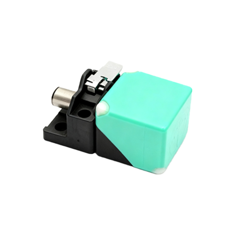
Many proximity sensors feature a potentiometer for adjusting sensitivity or the sensing distance. If the sensor is not detecting at the required range, or if it is triggering falsely, a sensitivity adjustment may be necessary. Using a target of the correct material and size, slowly adjust the potentiometer while bringing the target toward the sensor face. Mark the point where the output activates (the "operate point"). Then, slowly move the target away and mark the point where the output deactivates (the "release point"). The difference between these points is the hysteresis, which prevents output chatter. If the hysteresis is too small or the operate point is unstable, reduce the sensitivity slightly. Avoid setting sensitivity to the absolute maximum, as this can make the sensor susceptible to electrical noise, temperature drift, or detection of unintended objects.
Troubleshooting Common Interference Issues
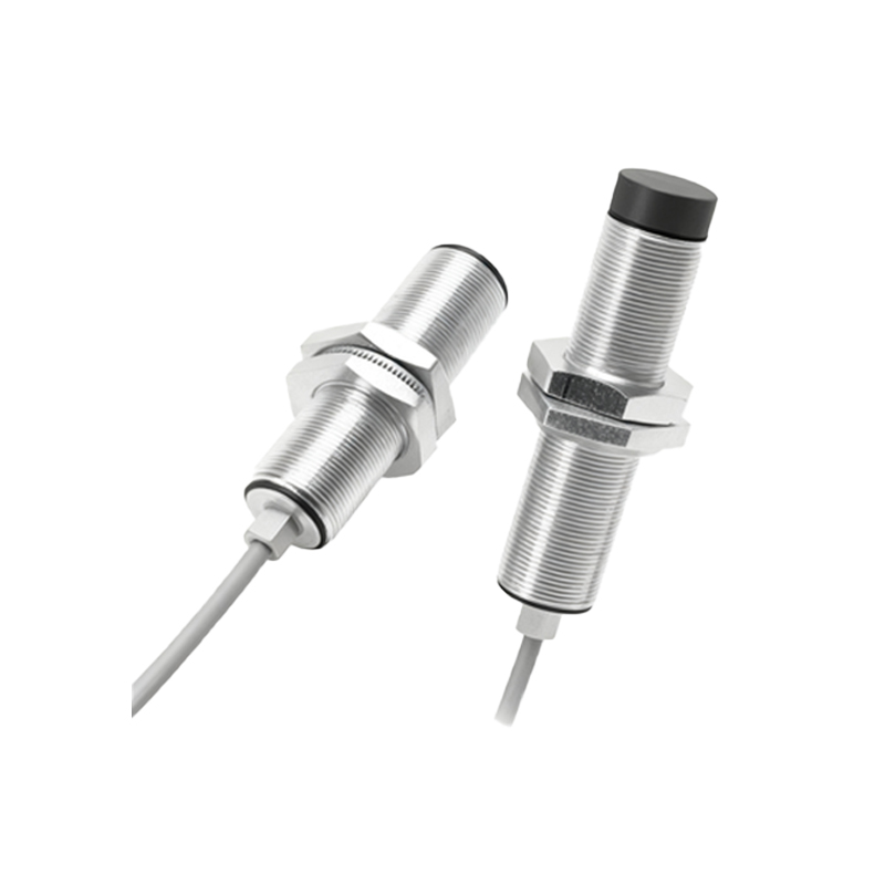
Electrical and environmental interference is a frequent culprit in sensor malfunction. For inductive sensors, ensure there are no other metal objects within the sensor's lateral or axial sensing area that could cause false triggering. For capacitive sensors, changes in humidity, moisture, or nearby materials can affect performance; adjust the sensitivity potentiometer and ensure proper grounding. Electrical noise from motors, variable frequency drives (VFDs), or welding equipment can be mitigated by using shielded cables, grounding the shield at the controller end only, installing ferrite cores, or routing sensor wires away from power lines. If multiple sensors are mounted closely, they may interfere with each other. Maintain a minimum spacing between sensors as recommended by the manufacturer, often 2-3 times the sensor diameter, or use sensors with built-in anti-interference technology.
Simulating Faults and Final Validation
After adjustments, conduct a series of tests to simulate real-world operating conditions and potential faults. Test the sensor across the entire range of expected target sizes, materials, and approach speeds. Verify that it does not trigger on non-target objects. For critical applications, test under minimum and maximum specified operating temperatures and voltage