Understanding Proximity Sensor Fundamentals
Proximity sensors are non-contact devices designed to detect the presence or absence of an object within a specified sensing range. The core principle involves emitting a field or beam and analyzing changes in the return signal. The "reading" of a sensor refers to the interpretation of its output signal to determine the state of detection. This output is not a direct measurement of distance in all cases but a state change triggered when an object enters the detection zone. The primary output types are digital (discrete) and analog. Digital outputs provide a simple ON/OFF signal, typically represented by a voltage shift (e.g., 0V for no object, 24V for object detected). Analog outputs provide a continuous signal, such as 4-20mA or 0-10V, which can be proportional to the distance between the sensor and the target. Understanding whether your sensor provides a discrete state or a continuous range value is the first critical step in reading it correctly.
Interpreting Digital Output Signals
For sensors with a digital (discrete) output, reading the data is straightforward but requires attention to electrical characteristics. A common configuration is a PNP (sourcing) or NPN (sinking) transistor output. A PNP sensor switches the positive voltage line to the load, while an NPN switches the negative or ground line. When reading the signal with a programmable logic controller (PLC), multimeter, or data acquisition card, you must match the input circuit type. The read value is binary: logic HIGH (often 24V DC) indicates target presence, and logic LOW (0V) indicates absence. However, it is crucial to consult the datasheet for the specific logic. Some sensors feature a "normally open" (NO) or "normally closed" (NC) configuration, which defines the output state when no target is present. A NO sensor outputs LOW when idle and HIGH when activated. Incorrect wiring or misunderstanding of this logic can lead to false readings and system faults.
Analyzing Analog Output and Scaling
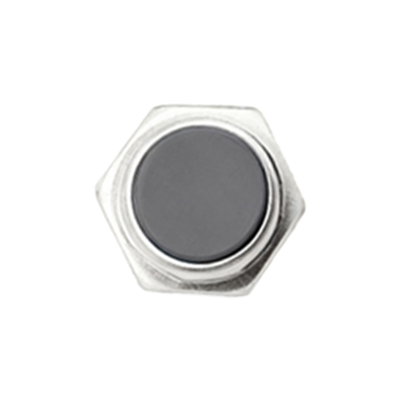
Analog-output proximity sensors provide a more nuanced reading, often correlating to the distance of the target. The standard industrial signals are 4-20mA current loops or 0-10V DC voltage. To read this data, you need an analog input module on your PLC or a capable measurement device. The raw value read from the module (e.g., a 12-bit integer from 0 to 4095) must be scaled to engineering units. This scaling process converts the electrical signal into a meaningful distance measurement. For instance, a sensor with a 10mm sensing range and a 4-20mA output might correspond to 4mA at 10mm distance and 20mA at 2mm distance. The scaling formula in the controller would map the input current to this distance range. Linearity, hysteresis, and temperature drift specified in the datasheet affect the accuracy of this reading. Regular calibration against known distances is recommended for precision applications.
Communication via IO-Link and Smart Sensors
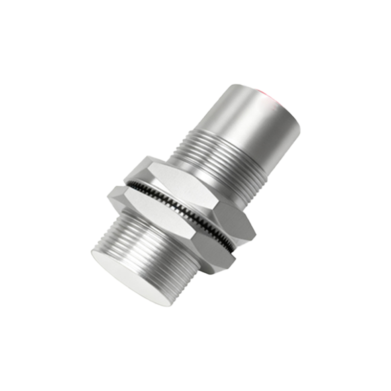
Modern "smart" proximity sensors often feature IO-Link communication, a point-to-point serial protocol that transmits far more data than a simple switch signal. Reading data from an IO-Link sensor involves connecting it to an IO-Link master module. Beyond the simple process data (cyclic ON/OFF state or analog value), you can read extensive parameter data (acyclic). This includes device identification, operating hours, temperature readings, signal strength, and detailed diagnostics like contamination warnings or switch cycle counters. To read this data, engineering software or a human-machine interface (HMI) configured for the device profile is used. This transforms the act of "reading" from a simple state check to a comprehensive health and status monitoring operation, enabling predictive maintenance and detailed process optimization.
Diagnosing Common Reading Errors and Noise
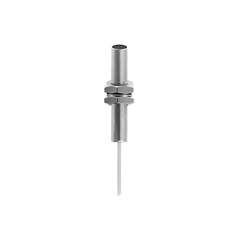
Incorrect readings often stem from electrical interference, improper installation, or unsuitable target material. Electrical noise from motors or variable frequency drives can induce false signals on analog lines or cause erratic digital switching. Using shielded cables, proper grounding, and separating signal lines from power lines are essential practices. For inductive sensors, the detection capability depends on the target's metal composition and size. A small or non-ferrous target may not be detected at the rated sensing distance, leading to a "no detection" reading when an object is present. For capacitive sensors, changes in humidity or surrounding material can affect the reading. Ultrasonic and photoelectric sensors can be fooled by acoustic noise, ambient light, or angled surfaces. Systematically checking the sensor's environment, target specifications, and electrical integrity is key to troubleshooting faulty readings.