Introduction to ST151 Photoelectric Sensor
The ST151 photoelectric sensor is a versatile and widely used device in industrial automation, designed for reliable object detection across various environments. This sensor operates on the principle of light beam interruption or reflection, making it suitable for applications such as conveyor belt monitoring, packaging systems, and assembly line control. Understanding its wiring configuration is crucial for ensuring optimal performance, safety, and longevity in electrical setups. This guide provides a detailed, step-by-step approach to wiring the ST151, covering essential components, connection methods, and troubleshooting tips to help engineers and technicians implement it effectively in their projects.
Components and Pin Configuration of ST151
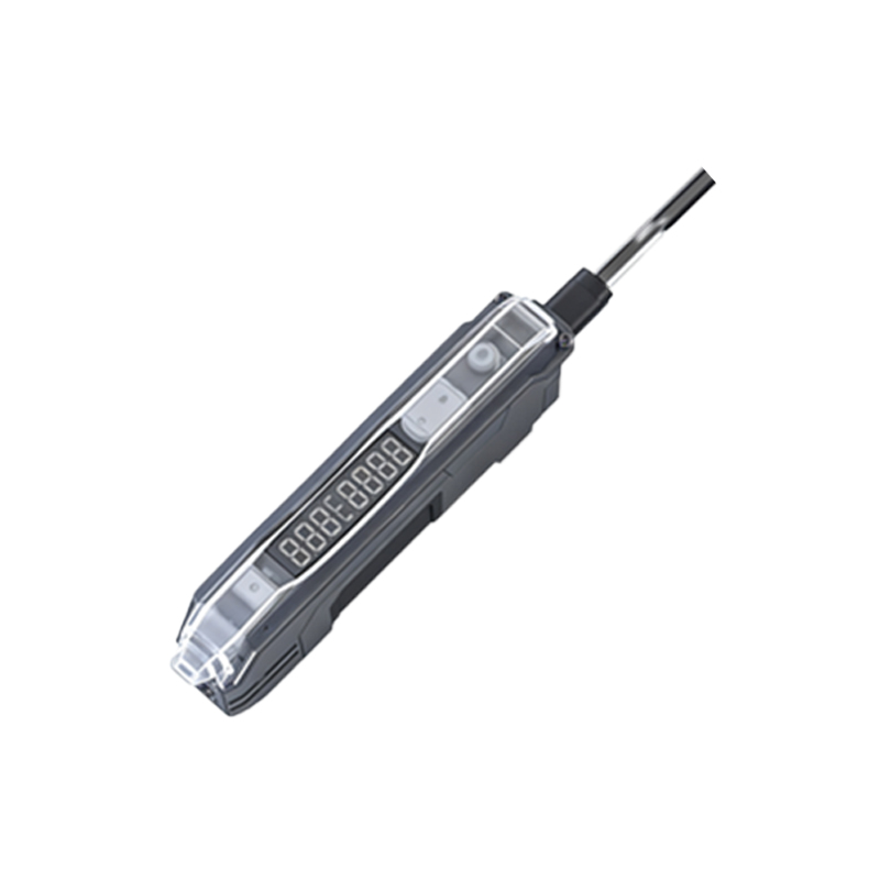
The ST151 photoelectric sensor typically features a compact housing with a built-in emitter and receiver, along with a wiring terminal block for electrical connections. Key components include the light source (often an LED), a phototransistor or photodiode receiver, and output circuitry. The pin configuration generally consists of three or four wires, depending on the model: brown wire for positive voltage supply (V+), blue wire for negative or ground (V-), black wire for output signal (NO or NC), and sometimes a white wire for complementary output or function selection. It is essential to refer to the specific datasheet for the ST151 variant, as pin assignments may vary by manufacturer. Always verify the labeling on the sensor body or documentation before proceeding with wiring to prevent damage or malfunction.
Required Tools and Safety Precautions
Before starting the wiring process, gather necessary tools such as wire strippers, screwdrivers, a multimeter for voltage testing, and appropriate cables (e.g., shielded cables for noise reduction). Safety is paramount in electrical work: ensure the power supply is disconnected during installation to avoid electric shock or short circuits. Wear protective gear like insulated gloves and safety glasses, and work in a dry, well-ventilated area. Check the sensor’s voltage rating (commonly 10-30V DC for the ST151) to match the power source, and avoid exceeding specified limits to prevent overheating or failure. Additionally, follow local electrical codes and industry standards to maintain a secure setup.
Step-by-Step Wiring Procedure
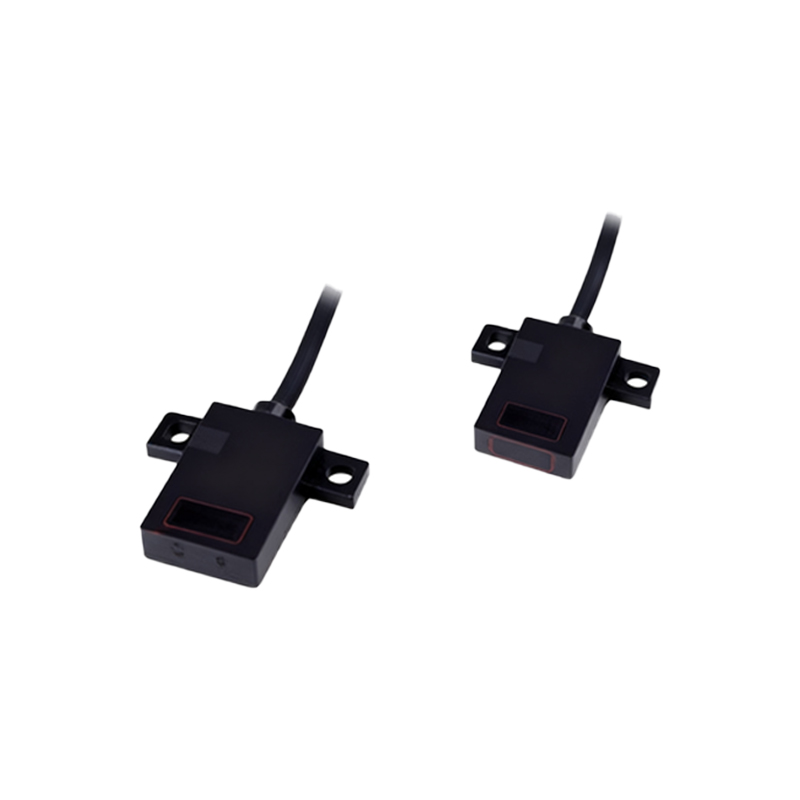
Begin by identifying the power source and load device (e.g., PLC, relay, or indicator). Connect the brown wire from the ST151 to the positive terminal of the DC power supply, and the blue wire to the negative terminal. For the output, link the black wire to the input of the load device; if using a normally open (NO) configuration, the output activates when an object is detected, while normally closed (NC) deactivates. If the sensor includes a white wire, consult the manual for its function—it may enable features like timing or output inversion. Use secure terminal connections and tighten screws to prevent loose wires, which can cause intermittent operation. After wiring, double-check all connections for accuracy and insulation to avoid exposed conductors.
Testing and Calibration After Wiring
Once wiring is complete, apply power to the system and observe the sensor’s indicator LEDs (if available). The ST151 usually has a power LED and an output status LED to signal operation. Test detection by placing an object within the sensing range; the output should trigger accordingly. Use a multimeter to measure voltage at the output wire, ensuring it switches between high and low states as expected. For calibration, adjust the sensitivity potentiometer on the sensor (if provided) to fine-tune detection for specific materials or distances, reducing false triggers. Perform multiple tests under actual operating conditions to verify reliability, and document settings for future maintenance.
Common Wiring Issues and Troubleshooting
If the ST151 fails to operate correctly after wiring, common issues may include incorrect polarity, loose connections, or environmental interference. Check that the brown and blue wires are not reversed, as this can damage the sensor. Inspect terminals for tightness and corrosion, and ensure cables are not damaged. Electrical noise from nearby motors or high-voltage equipment can cause erratic behavior; use shielded cables and ground the shield properly to mitigate this. If the output does not switch, verify the load compatibility and power supply voltage. Consult the sensor’s manual for error codes or LED patterns, and consider replacing the unit if persistent faults occur despite troubleshooting.
Best Practices for Installation and Maintenance
To maximize the ST151’s performance, install it in a stable location free from excessive vibration, dust, or moisture, using mounting brackets as needed. Align the emitter and receiver precisely for through-beam models, or set the correct angle for reflective types. Regularly clean the lens with a soft cloth to prevent dirt buildup that can reduce sensitivity. Schedule periodic inspections of wiring and connections, especially in harsh industrial environments, to detect wear or damage early. Keep spare sensors on hand for quick replacements, and train personnel on basic operation and safety protocols. By adhering to these practices, you can ensure long-term reliability and efficiency in automation systems.
Conclusion and Further Resources
Proper wiring of the ST151 photoelectric sensor is fundamental to its functionality in industrial applications. This guide has covered key aspects from pin configuration to troubleshooting, emphasizing safety and accuracy. For more detailed information, refer to the manufacturer’s documentation, technical datasheets, or online forums dedicated to automation engineering. Staying updated with industry advancements can help optimize sensor usage and integrate new features. If challenges arise, don’t hesitate to consult with experienced engineers or supplier support teams to resolve complex issues and enhance system performance.