Introduction to Photoelectric Sensing
Photoelectric sensors are ubiquitous in industrial automation, providing non-contact detection of objects based on the modulation of a light beam. Their core principle involves an emitter (light source) and a receiver. The sensor triggers an output signal when the presence, absence, or specific characteristics of a target object alters the received light. The diversity in their operating principles and physical configurations leads to distinct categories, each represented by standardized schematic icons in technical documentation and control system diagrams. Understanding these types and their corresponding symbols is crucial for proper selection, integration, and troubleshooting in electrical and control engineering.
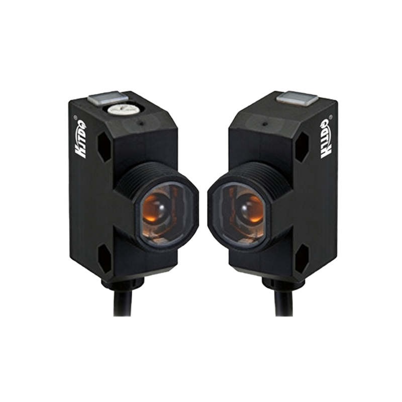
Through-Beam Sensors (Opposed Mode)
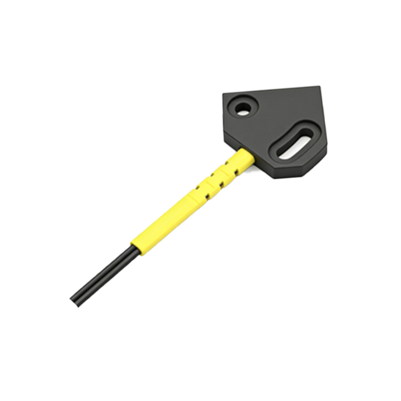
The through-beam, or opposed-mode, sensor consists of two separate units: a transmitter and a receiver positioned directly opposite each other. The transmitter emits a continuous or modulated light beam, which is received by the counterpart. An object is detected when it interrupts this beam. This configuration offers the longest sensing range and highest excess gain, making it highly reliable even in dirty environments or for detecting translucent objects. Its schematic icon typically depicts two separate rectangles or circles with inward-pointing arrows representing the light beam, connected by a dashed line. One symbol contains an LED-like emitter shape, the other a phototransistor shape, clearly indicating the separate components and the path of the beam.
Retroreflective Sensors
Retroreflective sensors house both the emitter and receiver in a single housing. They operate by projecting a light beam onto a specialized reflector, usually a corner-cube or tape reflector, which returns the light directly back to the receiver. Detection occurs when an object breaks this reflected beam. Their sensing range is shorter than through-beam but longer than diffuse sensors. A key challenge is distinguishing the target from highly reflective surfaces. The icon for this type shows a single unit with both emitter and receiver symbols, and a graphical representation of a reflector (often a triangle or a square with a diagonal line) at a distance, connected by a dashed line showing the beam's round trip.
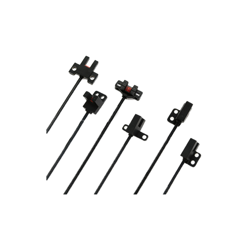
Diffuse Reflective Sensors (Proximity Mode)
Diffuse, or proximity, sensors also integrate the emitter and receiver into one device. However, they do not use a separate reflector. Instead, they detect the light beam diffusely reflected off the surface of the target object itself. This makes them simpler to install as only one device needs mounting, but sensing distance is limited and is highly dependent on the target's color, texture, and reflectivity. Light-colored objects are detected from farther away than dark, absorbent ones. The schematic icon is a single unit similar to the retroreflective symbol, but the dashed beam line terminates at an irregular shape representing the target object, without a dedicated reflector symbol.
Background Suppression Sensors
A specialized subset of diffuse sensors, Background Suppression (BGS) sensors use triangulation or focused optics to detect objects only within a precise, defined sensing window. They effectively ignore objects and surfaces beyond this set range (the background). This is invaluable for detecting objects on a conveyor belt or against a wall, ignoring the belt or wall itself. Icons for BGS sensors may look like standard diffuse symbols but are often annotated with text like "BGS" or include additional lines indicating the fixed focal point or suppression zone. Some detailed symbols show two light paths or a defined range bracket.
Fiber Optic Photoelectric Sensors
These sensors separate the amplifier (containing the actual emitter and receiver electronics) from the sensing point via flexible or rigid fiber optic cables. The cables guide light to and from the target area. This allows operation in extremely tight spaces, high-temperature zones, or areas with high electrical noise. Different sensing tips (through-beam, diffuse, etc.) can be attached to the cables. Their icons typically show a standard sensor amplifier symbol (e.g., for diffuse or through-beam) connected by a distinct line or cable symbol to a small tip or head graphic, indicating the remote sensing location.
Color Mark and Luminescence Sensors
Moving beyond simple presence detection, these advanced photoelectric sensors discriminate based on light properties. Color mark sensors detect specific color contrasts or marks by comparing reflected light intensities at different wavelengths. Luminescence sensors detect materials that fluoresce under UV light. Their icons are more complex, often incorporating wavelength symbols (like "λ"), color swatches, or specific notations like "UV" for luminescence types. They may resemble a diffuse sensor icon but with added graphical elements that signify the specialized analysis of the reflected light.
Laser Sensor Variants
While many photoelectric sensors use LEDs, laser-based variants employ a focused, coherent laser beam. This enables very precise detection, small spot sizes, and long ranges. They are commonly used in precision positioning, edge detection, and measurement applications. Icons for laser sensors are similar to their standard LED-based counterparts (through-beam, diffuse, etc.) but are distinguished by the inclusion of a laser symbol—often a circle with radiating lines or a specific annotation like "LASER" within the symbol.
Conclusion and Selection Guide
Choosing the correct photoelectric sensor type hinges on application requirements: required sensing distance, target characteristics, environmental conditions, and needed precision. The family of schematic icons serves as an immediate visual language for engineers. A through-beam icon signals a two-component, long-range setup. A single-unit icon with a reflector denotes retroreflective mode. A diffuse symbol indicates proximity sensing dependent on target reflectivity. Mastery of these symbols allows for rapid interpretation of system diagrams and ensures the specified sensor topology matches the physical and functional demands of the automation task, leading to robust and reliable system design.